6System connection (XD-951/XD-A900)
Connection of the System Accessories
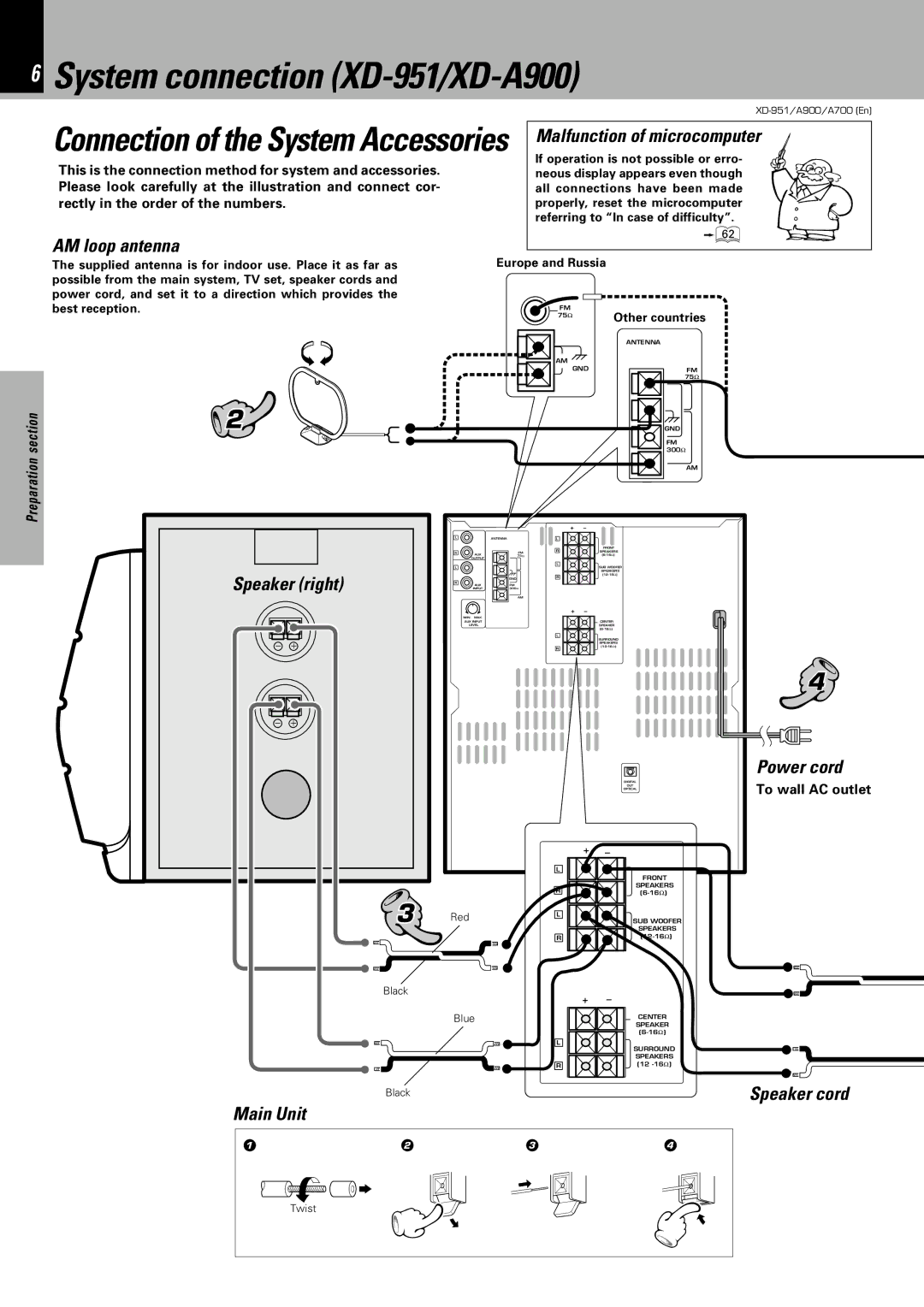
This is the connection method for system and accessories. Please look carefully at the illustration and connect cor- rectly in the order of the numbers.
AM loop antenna
Malfunction of microcomputer
If operation is not possible or erro- neous display appears even though all connections have been made properly, reset the microcomputer referring to “In case of difficulty”.
ã
Preparation section
The supplied antenna is for indoor use. Place it as far as possible from the main system, TV set, speaker cords and power cord, and set it to a direction which provides the best reception.
2 |
|
Speaker (right) | |
− | + |
− | + |
Europe and Russia
FM | Other countries |
75Ω | |
| |
| ANTENNA |
AM
GND | FM |
75Ω
GND
FM 300Ω
AM
|
|
| + | – |
L | ANTENNA |
| L |
|
|
|
| R | FRONT |
R | AUX | FM | SPEAKERS | |
| 75Ω |
| ||
| OUTPUT |
|
|
|
L |
|
| L | SUB WOOFER |
|
|
| ||
|
|
|
| SPEAKERS |
|
|
| R | |
|
| GND |
| |
R | AUX | FM |
|
|
| INPUT | 300Ω |
|
|
|
| AM |
|
|
|
|
| + | – |
| MIN. MAX. |
|
|
|
| AUX INPUT |
|
| CENTER |
| LEVEL |
|
| SPEAKER |
|
|
|
| |
|
|
| L | SURROUND |
|
|
|
| |
|
|
|
| SPEAKERS |
|
|
| R | |
|
|
|
|
DIGITAL
OUT
OPTICAL
4
Power cord
To wall AC outlet
Application section
sections
3 |
Black |
Black |
Red
Blue
L
R
L
R
L
R
+ | – |
+ | – |
FRONT
SPEAKERS
SUB WOOFER
SPEAKERS
CENTER
SPEAKER
SURROUND SPEAKERS (12
Speaker cord
Knowledge
Main Unit
1 | 2 | 3 | 4 |
Twist
