Operation
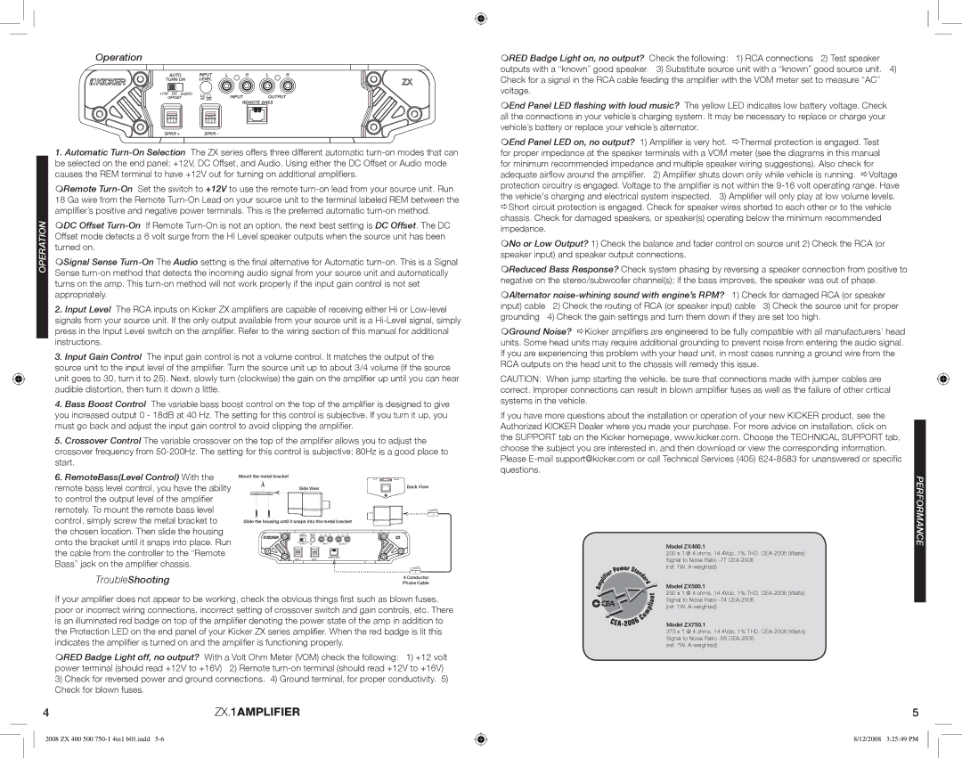
| | AUTO | | INPUT | L | R | L | R |
| | TURN ON | | LEVEL | | | | |
| | +12V DC AUDIO | LO | INPUT | | OUTPUT | |
| | OFFSET | | | |
| | | HI | REMOTE BASS | |
| | | | | |
| | SPKR + | | SPKR - | | | | |
| | 1. Automatic Turn-On Selection | The ZX series offers three different automatic turn-on modes that can |
| | be selected on the end panel; +12V, DC Offset, and Audio. Using either the DC Offset or Audio mode |
| | causes the REM terminal to have +12V out for turning on additional amplifiers. |
| | Remote Turn-OnSet the switch to +12V to use the remote turn-on lead from your source unit. Run |
| | 18 Ga wire from the Remote Turn-On Lead on your source unit to the terminal labeled REM between the |
| | amplifier’s positive and negative power terminals. This is the preferred automatic turn-on method. |
| OPERATION | DC Offset Turn-OnIf Remote Turn-On is not an option, the next best setting is DC Offset. The DC |
| Offset mode detects a 6 volt surge from the HI Level speaker outputs when the source unit has been |
| |
turned on.
Signal Sense Turn-OnThe Audio setting is the final alternative for Automatic turn-on. This is a Signal Sense turn-on method that detects the incoming audio signal from your source unit and automatically turns on the amp. This turn-on method will not work properly if the input gain control is not set appropriately.
2. Input Level The RCA inputs on Kicker ZX amplifiers are capable of receiving either Hi or Low-level signals from your source unit. If the only output available from your source unit is a Hi-Level signal, simply press in the Input Level switch on the amplifier. Refer to the wiring section of this manual for additional instructions.
3. Input Gain Control The input gain control is not a volume control. It matches the output of the source unit to the input level of the amplifier. Turn the source unit up to about 3/4 volume (if the source unit goes to 30, turn it to 25). Next, slowly turn (clockwise) the gain on the amplifier up until you can hear audible distortion, then turn it down a little.
4. Bass Boost Control The variable bass boost control on the top of the amplifier is designed to give you increased output 0 - 18dB at 40 Hz. The setting for this control is subjective. If you turn it up, you must go back and adjust the input gain control to avoid clipping the amplifier.
5. Crossover Control The variable crossover on the top of the amplifier allows you to adjust the crossover frequency from 50-200Hz. The setting for this control is subjective; 80Hz is a good place to start.
RED Badge Light on, no output? Check the following: 1) RCA connections 2) Test speaker outputs with a “known” good speaker. 3) Substitute source unit with a “known” good source unit. 4) Check for a signal in the RCA cable feeding the amplifier with the VOM meter set to measure “AC” voltage.
End Panel LED flashing with loud music? The yellow LED indicates low battery voltage. Check all the connections in your vehicle’s charging system. It may be necessary to replace or charge your vehicle’s battery or replace your vehicle’s alternator.
End Panel LED on, no output? 1) Amplifier is very hot. ÖThermal protection is engaged. Test for proper impedance at the speaker terminals with a VOM meter (see the diagrams in this manual for minimum recommended impedance and multiple speaker wiring suggestions). Also check for adequate airflow around the amplifier. 2) Amplifier shuts down only while vehicle is running. ÖVoltage protection circuitry is engaged. Voltage to the amplifier is not within the 9-16 volt operating range. Have the vehicle's charging and electrical system inspected. 3) Amplifier will only play at low volume levels. ÖShort circuit protection is engaged. Check for speaker wires shorted to each other or to the vehicle chassis. Check for damaged speakers, or speaker(s) operating below the minimum recommended impedance.
No or Low Output? 1) Check the balance and fader control on source unit 2) Check the RCA (or speaker input) and speaker output connections.
Reduced Bass Response? Check system phasing by reversing a speaker connection from positive to negative on the stereo/subwoofer channel(s); if the bass improves, the speaker was out of phase.
Alternator noise-whining sound with engine’s RPM? 1) Check for damaged RCA (or speaker
input) cable | 2) Check the routing of RCA (or speaker input) cable 3) Check the source unit for proper |
grounding | 4) Check the gain settings and turn them down if they are set too high. |
Ground Noise? ÖKicker amplifiers are engineered to be fully compatible with all manufacturers’ head units. Some head units may require additional grounding to prevent noise from entering the audio signal. If you are experiencing this problem with your head unit, in most cases running a ground wire from the RCA outputs on the head unit to the chassis will remedy this issue.
CAUTION: When jump starting the vehicle, be sure that connections made with jumper cables are correct. Improper connections can result in blown amplifier fuses as well as the failure of other critical systems in the vehicle.
If you have more questions about the installation or operation of your new KICKER product, see the Authorized KICKER Dealer where you made your purchase. For more advice on installation, click on the SUPPORT tab on the Kicker homepage, www.kicker.com. Choose the TECHNICAL SUPPORT tab, choose the subject you are interested in, and then download or view the corresponding information. Please E-mail support@kicker.com or call Technical Services (405) 624-8583 for unanswered or specific questions.