Hardware Installation | 5 |
Hardware Installation
Before you begin installing network cables, please take a few moments to familiarize yourself with the EtheRx
Front Panel
Utilization LEDs |
|
|
|
|
|
|
|
|
|
|
|
| UTP Ports |
|
| |||||
|
|
| Collision LEDs |
|
|
|
|
|
|
|
|
|
|
|
| |||||
|
|
|
|
|
|
| KNE16TP/RS |
|
|
| 1 | 2 | 3 | 4 | 5 | 6 | 7 | 8 |
| |
|
|
|
|
|
|
|
|
|
|
|
|
|
|
|
|
|
|
| ||
|
|
|
| LINK / ACT / PARTITION |
|
|
|
|
|
|
|
|
|
|
| CABLE TYPE | ||||
|
|
| 1 | 2 3 4 | 5 6 7 8 |
|
|
|
|
|
|
|
|
|
|
| ||||
| UTIL % |
|
|
|
|
|
|
|
|
|
|
|
|
|
|
|
| |||
PWR |
| AUI | BNC |
|
|
|
|
|
|
|
|
|
|
|
|
|
|
|
|
|
| COLL % |
|
|
|
| 9 | 10 11 12 | 13 14 15 16 |
|
|
| 9 | 10 | 11 | 12 | 13 | 14 | 15 | 16 | CASCADE |
|
|
|
|
|
|
|
|
|
|
|
| |||||||||
|
|
|
|
|
|
|
| 1 | 2 | 3 | 4 | 5 | 6 | 7 | 8 | 9 | 10 | 11 | 12 |
|
|
|
|
|
|
|
| KNE24TP/RS |
|
|
|
|
|
|
|
|
|
|
|
| |
|
|
| LINK / ACT / PARTITION |
|
|
|
|
|
|
|
|
|
|
|
| CABLE TYPE | ||||
1 | 2 3 | 4 | 5 | 6 7 8 | 9 10 11 12 |
|
|
|
|
|
|
|
|
|
|
| ||||
| UTIL % |
|
|
|
|
|
|
|
|
|
|
|
|
| ||||||
PWR |
| AUI | BNC |
|
|
|
|
|
|
|
|
|
|
|
|
|
|
|
|
|
| COLL % |
| 13 14 15 16 | 17 18 19 20 | 21 22 23 24 | 14 | 15 | 16 | 17 | 18 | 19 | 20 | 21 | 22 | 23 | 24 |
| |||
|
|
|
|
|
|
|
| 13 | CASCADE | |||||||||||
Power | AUI |
|
|
|
|
|
|
|
|
|
|
|
|
|
|
|
|
|
|
|
LED |
|
|
|
|
|
|
|
|
|
|
|
|
|
|
|
| Cascade Switch | |||
LED | BNC |
|
|
| Link /Activity / Partition | UTP Ports |
|
| ||||||||||||
|
|
|
|
|
| |||||||||||||||
|
| LED |
|
|
|
| LEDs |
|
|
|
|
|
|
|
|
|
| |||
|
|
|
|
|
|
|
|
|
|
|
|
|
|
|
|
|
| |||
|
|
|
|
|
|
|
|
|
|
|
|
|
|
|
|
|
|
| ||
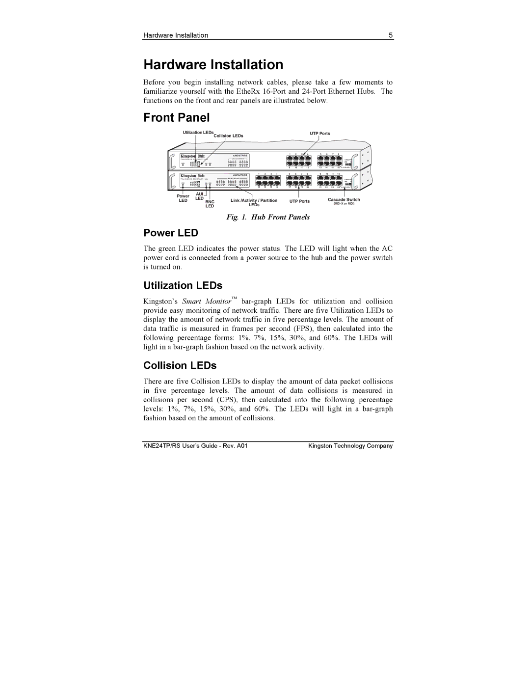
Fig. 1. Hub Front Panels
Power LED
The green LED indicates the power status. The LED will light when the AC power cord is connected from a power source to the hub and the power switch is turned on.
Utilization LEDs
Kingston’s Smart Monitor™
Collision LEDs
There are five Collision LEDs to display the amount of data packet collisions in five percentage levels. The amount of data collisions is measured in collisions per second (CPS), then calculated into the following percentage levels: 1%, 7%, 15%, 30%, and 60%. The LEDs will light in a
KNE24TP/RS User’s Guide - Rev. A01 | Kingston Technology Company |