Network Configurations 11

KNE24TP/RS User’s Guide - Rev. A01 Kingston Technology Company
Linear Bus Network

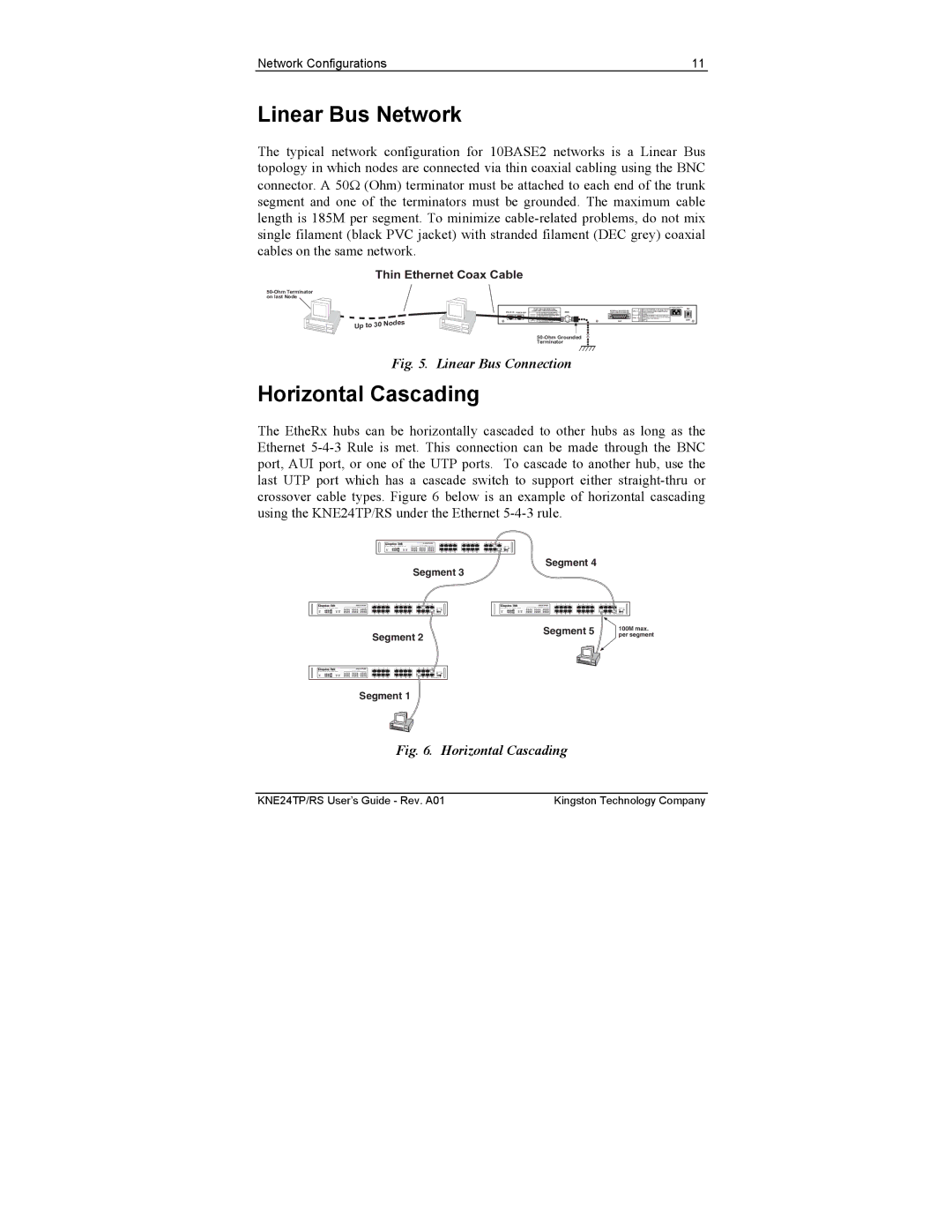
The typical network configuration for 10BASE2 networks is a Linear Bus

topology in which nodes are connected via thin coaxial cabling using the BNC

connector. A 50 (Ohm) terminator must be attached to each end of the trunk

segment and one of the terminators must be grounded. The maximum cable

length is 185M per segment. To minimize cable-related problems, do not mix

single filament (black PVC jacket) with stranded filament (DEC grey) coaxial

cables on the same network.

Thin Ethernet Coax Cable
Up to 30 Nodes50-Ohm GroundedTerminatorSTACK-INSTACK-OUTAUIOFFON
100-240VAC 50-60HZ 1A
EXTERNAL TRANSCEIVER
( SQE JUMPER DISABLED)
UTILIZATION % - Bar graph indication
(in percentage) of the traffic rate in
reference to the 10 Mbps Ethernet
bandwidth.
COLL %
UTIL %
1%
7%
15%
30%
60%
1%
7%
15%
30%
60%
Green
Green
Green
Amber
Orange
Amber
Amber
Amber
Amber
Red
COLLISION % - Bargraph indication
(in percentage) of the packet collision
rate in the network.
PORT #16 OR PORT #24CASCADE CONFIGURATION
For cascading to another MDI-X
hub port using straight-thru cable.
For connection to workstation NIC
using cross-over cable.
For cascading to another MDI-X
hub port using cross-over cable.
For connection to workstation NIC
using straight-thru cable.
BNC50-Ohm Terminatoron last Node

Fig. 5. Linear Bus Connection

Horizontal Cascading

The EtheRx hubs can be horizontally cascaded to other hubs as long as the

Ethernet 5-4-3 Rule is met. This connection can be made through the BNC

port, AUI port, or one of the UTP ports. To cascade to another hub, use the

last UTP port which has a cascade switch to support either straight-thru or

crossover cable types. Figure 6 below is an example of horizontal cascading

using the KNE24TP/RS under the Ethernet 5-4-3 rule.

Slick-Stack Ethernet Hub
KNE24TP/RS
AUIBNC
34
21
PWR
UTIL %
COLL %
LINK / ACT / PARTITION
1 2 3 45 6 7 8 9 10 11 12
13 14 15 1617 18 19 20 21 22 23 24
1516
1413 1920
1817
78
6511
12
109
2122 23 24 CASCADE
CABLE TYPE
234567
88
Segment 1Segment 2Segment 3 Segment 4Segment 5
Slick-Stack Ethernet Hub
KNE24TP/RS
AUIBNC
34
21
PWR
UTIL %
COLL %
LINK / ACT / PARTITION
1 2 3 45 6 7 8 9 10 11 12
13 14 15 1617 18 19 20 21 22 23 24
1516
1413 1920
1817
78
6511
12
109
2122 23 24 CASCADE
CABLE TYPE
Slick-Stack Ethernet Hub
KNE24TP/RS
AUIBNC
34
21
PWR
UTIL %
COLL %
LINK / ACT / PARTITION
1 2 3 45 6 7 8 9 10 11 12
13 14 15 1617 18 19 20 21 22 23 24
1516
1413 1920
1817
78
6511
12
109
2122 23 24 CASCADE
CABLE TYPE
Slick-Stack Ethernet Hub
KNE24TP/RS
AUIBNC
34
21
PWR
UTIL %
COLL %
LINK / ACT / PARTITION
1 2 3 45 6 7 8 9 10 11 12
13 14 15 1617 18 19 20 21 22 23 24
1516
1413 1920
1817
78
6511
12
109
2122 23 24 CASCADE
CABLE TYPE
100M max.per segment

Fig. 6. Horizontal Cascading