8. Using 2 or more people, remove cardboard or hardboard from under range.
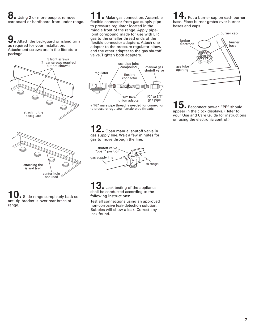
9. Attach the backguard or island trim as required for your installation. Attachment screws are in the literature package.
3 front screws
(4 rear screws required
but not shown)
11. Make gas connection. Assemble flexible connector from gas supply pipe to pressure regulator located in the middle front of the range. Apply pipe- joint compound made for use with L.P. gas to the smaller thread ends of the flexible connector adapters. Attach one adapter to the pressure regulator elbow and the other adapter to the gas shutoff valve. Tighten both adapters.
use
compound manual gas shutoff valve
regulator flexible connector
14. Put a burner cap on each burner base. Place burner grates over burner bases and caps.
| burner cap | |
ignitor | burner | |
electrode | ||
base | ||
|
gas tube opening
attaching the
backguard
attaching the
island trim
center hole
not used
10. Slide range completely back so
1/2" flare | 1/2" to 3/4" |
union adapter | gas pipe |
a 1/2" male pipe thread is needed for connection to pressure regulator female pipe threads
12. Open manual shutoff valve in gas supply line. Wait a few minutes for gas to move through the line.
shutoff valve
“open” position
gas supply line
to range
13. Leak testing of the appliance shall be conducted according to the following instructions:
Test all connections using an approved
15. Reconnect power. “PF” should appear in the clock displays. (Refer to your Use and Care Guide for instructions on using the electronic control.)
7