Cable Assembly | 16 |
|
|
|
|
|
|
|
|
| |
|
|
|
| 63 |
|
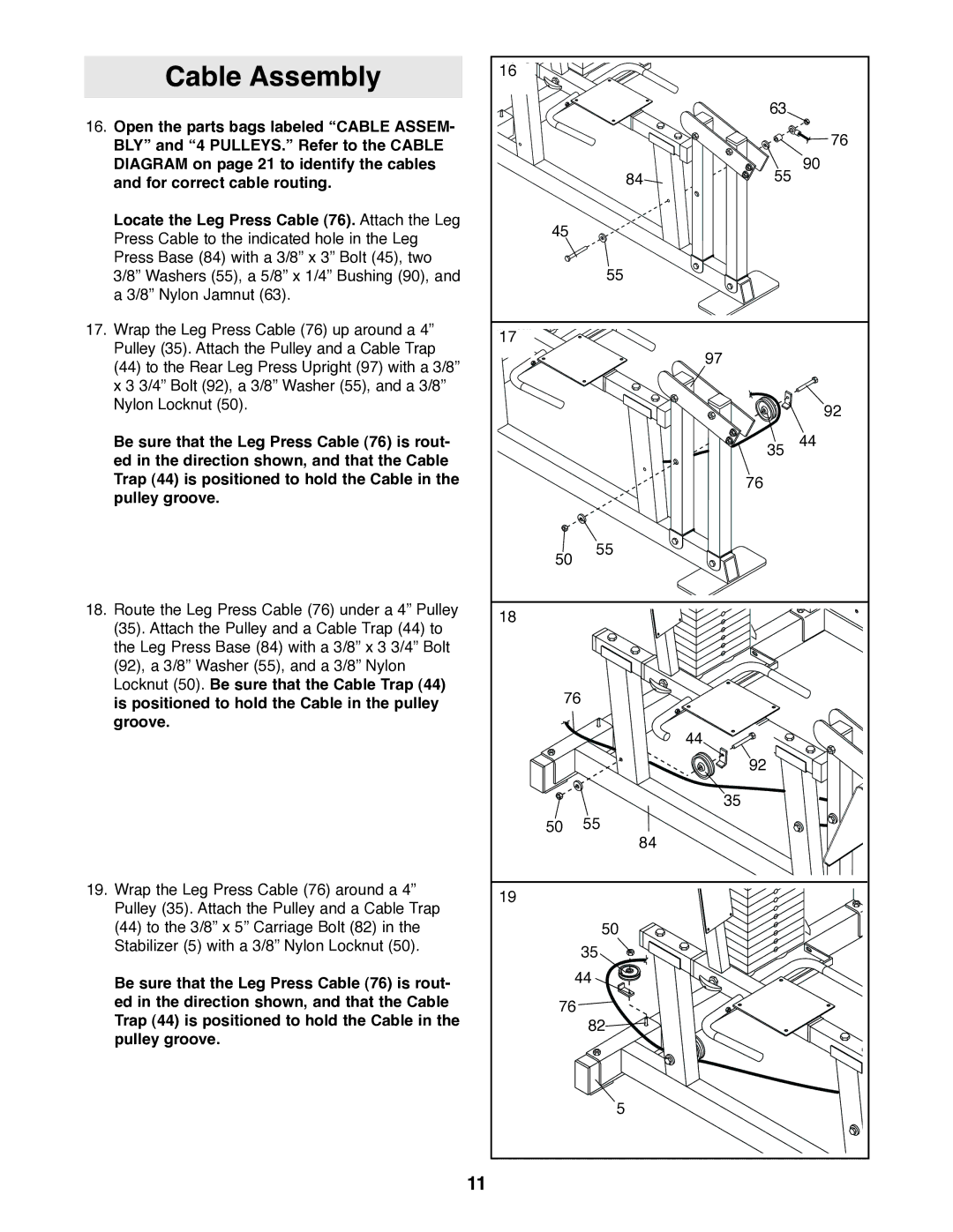
16. Open the parts bags labeled “CABLE ASSEM- |
|
|
|
| 76 |
BLY” and “4 PULLEYS.” Refer to the CABLE |
|
|
|
| |
|
|
|
|
| |
DIAGRAM on page 21 to identify the cables |
|
| 84 | 55 | 90 |
and for correct cable routing. |
|
|
| ||
Locate the Leg Press Cable (76). Attach the Leg | 45 |
|
|
| |
Press Cable to the indicated hole in the Leg |
|
|
| ||
|
|
|
|
| |
Press Base (84) with a 3/8” x 3” Bolt (45), two |
|
| 55 |
|
|
3/8” Washers (55), a 5/8” x 1/4” Bushing (90), and |
|
|
|
| |
a 3/8” Nylon Jamnut (63). |
|
|
|
|
|
17. Wrap the Leg Press Cable (76) up around a 4” | 17 |
|
|
|
|
Pulley (35). Attach the Pulley and a Cable Trap |
|
|
|
| |
|
|
| 97 |
| |
(44) to the Rear Leg Press Upright (97) with a 3/8” |
|
|
|
| |
|
|
|
|
| |
x 3 3/4” Bolt (92), a 3/8” Washer (55), and a 3/8” |
|
|
|
|
|
Nylon Locknut (50). |
|
|
|
| 92 |
|
|
|
|
| |
Be sure that the Leg Press Cable (76) is rout- |
|
|
| 35 | 44 |
ed in the direction shown, and that the Cable |
|
|
|
|
|
Trap (44) is positioned to hold the Cable in the |
|
|
| 76 |
|
pulley groove. |
|
|
|
|
|
| 50 | 55 |
|
| |
|
|
|
| ||
18. Route the Leg Press Cable (76) under a 4” Pulley | 18 |
|
|
|
|
(35). Attach the Pulley and a Cable Trap (44) to |
|
|
|
| |
|
|
|
|
| |
the Leg Press Base (84) with a 3/8” x 3 3/4” Bolt |
|
|
|
|
|
(92), a 3/8” Washer (55), and a 3/8” Nylon |
|
|
|
|
|
Locknut (50). Be sure that the Cable Trap (44) |
| 76 |
|
|
|
is positioned to hold the Cable in the pulley |
|
|
|
| |
groove. |
|
|
| 44 |
|
|
|
|
|
| |
|
|
|
| 92 |
|
|
|
|
| 35 |
|
| 50 |
| 55 |
|
|
|
|
| 84 |
|
|
19. Wrap the Leg Press Cable (76) around a 4” | 19 |
|
|
|
|
Pulley (35). Attach the Pulley and a Cable Trap |
|
|
|
| |
|
|
|
|
| |
(44) to the 3/8” x 5” Carriage Bolt (82) in the |
|
| 50 |
|
|
Stabilizer (5) with a 3/8” Nylon Locknut (50). |
|
| 35 |
|
|
|
|
|
|
| |
Be sure that the Leg Press Cable (76) is rout- |
| 44 |
|
| |
|
|
|
|
| |
ed in the direction shown, and that the Cable | 76 |
|
|
| |
Trap (44) is positioned to hold the Cable in the |
|
|
| ||
|
| 82 |
|
| |
pulley groove. |
|
|
|
| |
|
|
|
|
| |
|
|
| 5 |
|
|
| 11 |
|
|
|
|
