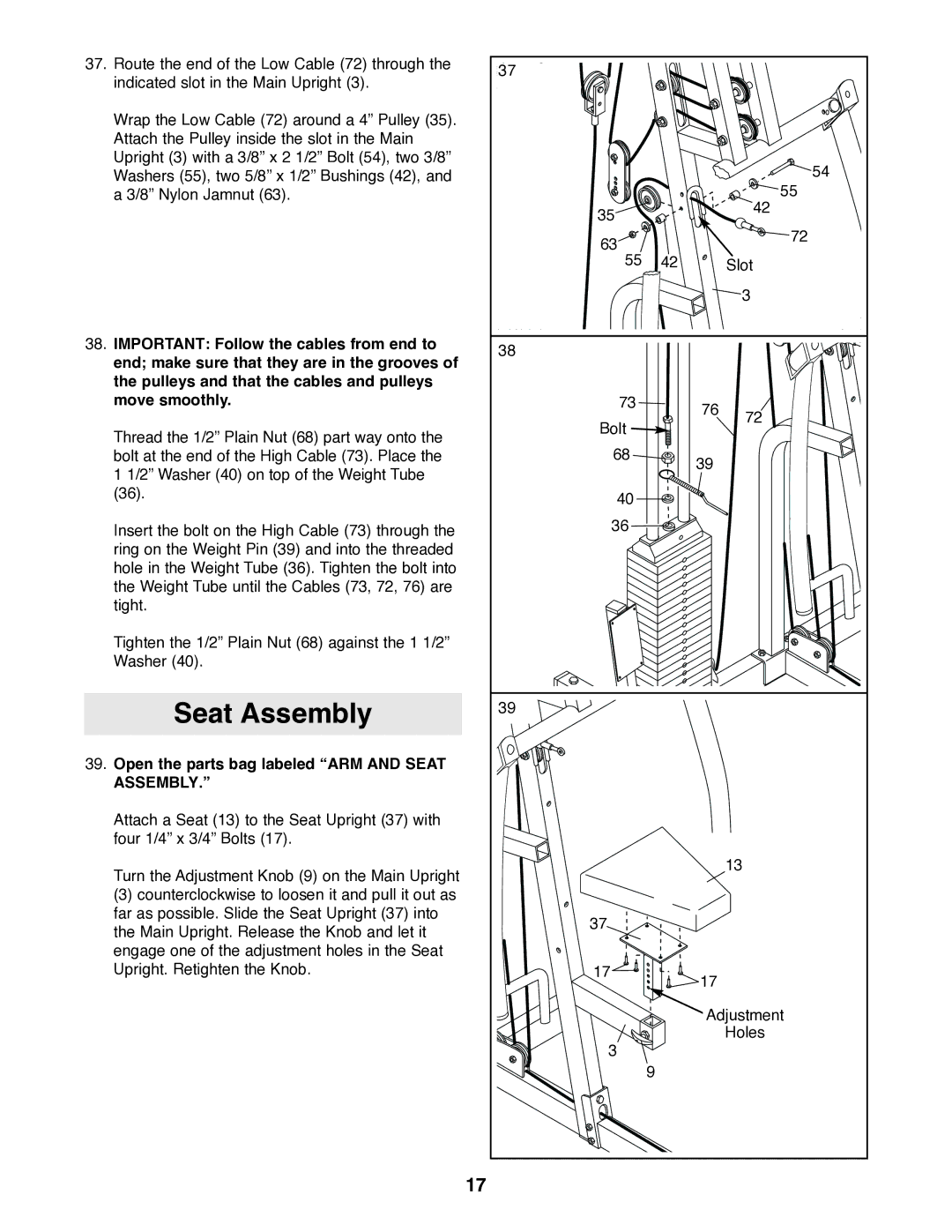
37. Route the end of the Low Cable (72) through the | 37 |
|
|
|
indicated slot in the Main Upright (3). |
|
|
| |
|
|
|
| |
Wrap the Low Cable (72) around a 4” Pulley (35). |
|
|
|
|
Attach the Pulley inside the slot in the Main |
|
|
|
|
Upright (3) with a 3/8” x 2 1/2” Bolt (54), two 3/8” |
|
|
| 54 |
Washers (55), two 5/8” x 1/2” Bushings (42), and |
|
|
| |
a 3/8” Nylon Jamnut (63). |
|
|
| 55 |
| 35 |
|
| 42 |
|
|
|
| |
| 63 |
|
| 72 |
|
|
|
| |
| 55 | 42 |
| Slot |
|
|
|
| 3 |
38. IMPORTANT: Follow the cables from end to | 38 |
|
|
|
end; make sure that they are in the grooves of |
|
|
| |
|
|
|
| |
the pulleys and that the cables and pulleys |
|
|
|
|
move smoothly. | 73 |
| 76 | 72 |
|
|
| ||
| Bolt |
|
| |
Thread the 1/2” Plain Nut (68) part way onto the |
|
|
| |
68 |
|
|
| |
bolt at the end of the High Cable (73). Place the |
| 39 |
| |
1 1/2” Washer (40) on top of the Weight Tube |
|
|
| |
|
|
|
| |
(36). | 40 |
|
|
|
|
|
|
| |
Insert the bolt on the High Cable (73) through the | 36 |
|
|
|
|
|
|
| |
ring on the Weight Pin (39) and into the threaded |
|
|
|
|
hole in the Weight Tube (36). Tighten the bolt into |
|
|
|
|
the Weight Tube until the Cables (73, 72, 76) are |
|
|
|
|
tight. |
|
|
|
|
Tighten the 1/2” Plain Nut (68) against the 1 1/2” |
|
|
|
|
Washer (40). |
|
|
|
|
Seat Assembly | 39 |
|
|
|
|
|
|
| |
39. Open the parts bag labeled “ARM AND SEAT |
|
|
|
|
ASSEMBLY.” |
|
|
|
|
Attach a Seat (13) to the Seat Upright (37) with |
|
|
|
|
four 1/4” x 3/4” Bolts (17). |
|
|
|
|
Turn the Adjustment Knob (9) on the Main Upright |
|
|
| 13 |
|
|
|
| |
(3) counterclockwise to loosen it and pull it out as |
|
|
|
|
far as possible. Slide the Seat Upright (37) into | 37 |
|
|
|
the Main Upright. Release the Knob and let it |
|
|
| |
|
|
|
| |
engage one of the adjustment holes in the Seat |
|
|
|
|
Upright. Retighten the Knob. | 17 |
| 17 |
|
|
|
|
| |
|
|
| Adjustment | |
|
|
|
| Holes |
| 3 |
|
|
|
|
| 9 |
|
|
| 17 |
|
|
|
