10DN9610 AES50 Repeater
3.4 Powering the unit
◊To ensure redundancy, each DC inlet is to be sourced from its own separate branch circuit. Otherwise, their mains sources must be suitably distributed so as to meet local safety regulations.
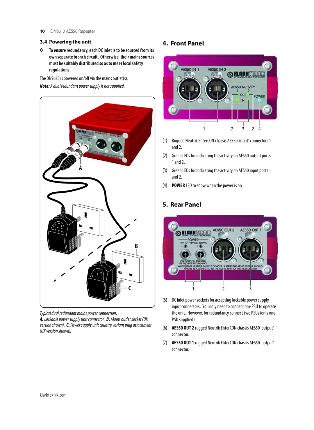
The DN9610 is powered on/off via the mains outlet(s).
Note: A dual redundant power supply is not supplied.
A
4. Front Panel
1 | 2 | 3 | 2 | 4 |
(1)Rugged Neutrik EhterCON chassis AES50 'input' connectors 1 and 2.
(2)Green LEDs for indicating the activity on AES50 output ports 1 and 2.
(3)Green LEDs for indicating the activity on AES50 input ports 1 and 2.
(4)POWER LED to show when the power is on.
5. Rear Panel
B
C
Typical dual redundant mains power connection.
A. Lockable power supply unit connector. B. Mains outlet socket (UK version shown). C. Power supply unit country variant plug attachment (UK version shown).
123
(5)DC inlet power sockets for accepting lockable power supply input connectors. You only need to connect one PSU to operate the unit. However, for redundancy connect two PSUs (only one PSU supplied).
(6)AES50 OUT 2 rugged Neutrik EhterCON chassis AES50 'output' connector.
(7)AES50 OUT 1 rugged Neutrik EhterCON chassis AES50 'output' connector.
klarkteknik.com