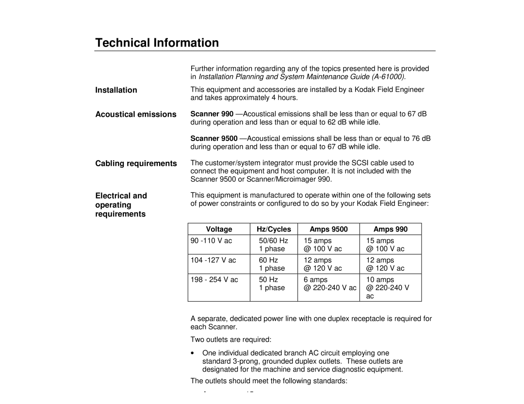
9500, 990 specifications
The Kodak 9500 is a sophisticated imaging device designed to revolutionize the way professionals engage with photography and imaging technologies. This innovative product combines cutting-edge technology with user-friendly features to enhance the overall shooting experience, making it a top choice among photographers and videographers alike.One of the standout features of the Kodak 9500 is its high-resolution sensor, which captures images in stunning detail. With a resolution of up to 50 megapixels, this camera allows photographers to produce exceptionally sharp and vibrant photos, making it an ideal choice for commercial photography, fine art, and even landscape photography. The larger pixel size ensures better performance in low-light conditions, allowing for clearer images without the noise that often plagues other cameras.
The Kodak 9500 also boasts an advanced autofocus system. This system employs phase detection technology, ensuring that subjects are locked in focus quickly and accurately, even in dynamic environments. Whether capturing fast-moving wildlife or bustling street scenes, users can rely on the camera's autofocus capabilities to deliver crisp, clear results every time.
Another key feature of the Kodak 9500 is its versatility in terms of shooting modes. The camera offers a wide range of options, including manual, aperture priority, and shutter priority modes. Additionally, the inclusion of various scene modes enables users to achieve optimal results regardless of their level of expertise. This makes the Kodak 9500 accessible to both beginners and seasoned photographers.
In terms of connectivity, the Kodak 9500 incorporates built-in Wi-Fi and Bluetooth technology, allowing for easy sharing of images and videos. Photographers can transfer their work directly to smartphones or tablets and share them on social media platforms without the need for additional software or wires. This seamless connectivity enhances the workflow for professionals who need to present their work quickly.
The build quality of the Kodak 9500 is another aspect worth mentioning. Constructed with a durable magnesium alloy body, the camera is designed to withstand the rigors of professional use. It is also weather-sealed, making it resistant to moisture and dust, allowing photographers to work confidently in various environmental conditions.
In summary, the Kodak 9500 stands out in the crowded camera market with its high-resolution capabilities, advanced autofocus system, versatile shooting modes, and robust connectivity options. Its durable construction makes it a reliable tool for professionals seeking to capture their vision with precision and clarity. Whether you are a seasoned pro or a passionate enthusiast, the Kodak 9500 is an exceptional choice that elevates the art of photography.
