SERVICE MANUAL
Adjusting the ZERO POSITION SWITCH
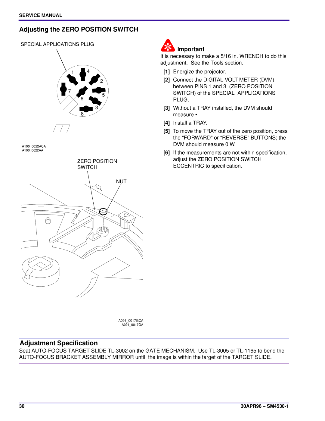
SPECIAL APPLICATIONS PLUG
1 4
2
7
5
6
3
8
A100_0022ACA
A100_0022AA
ZERO POSITION
SWITCH
NUT
![]() Important
Important
It is necessary to make a 5/16 in. WRENCH to do this adjustment. See the Tools section.
[1]Energize the projector.
[2]Connect the DIGITAL VOLT METER (DVM) between PINS 1 and 3 (ZERO POSITION SWITCH) of the SPECIAL APPLICATIONS PLUG.
[3]Without a TRAY installed, the DVM should measure •.
[4]Install a TRAY.
[5]To move the TRAY out of the zero position, press the “FORWARD” or “REVERSE” BUTTONS; the DVM should measure 0 W.
[6]If the measurements are not within specification, adjust the ZERO POSITION SWITCH ECCENTRIC to specification.
A091_0017GCA
A091_0017GA
Adjustment Specification
Seat
30 | 30APR96 – |
