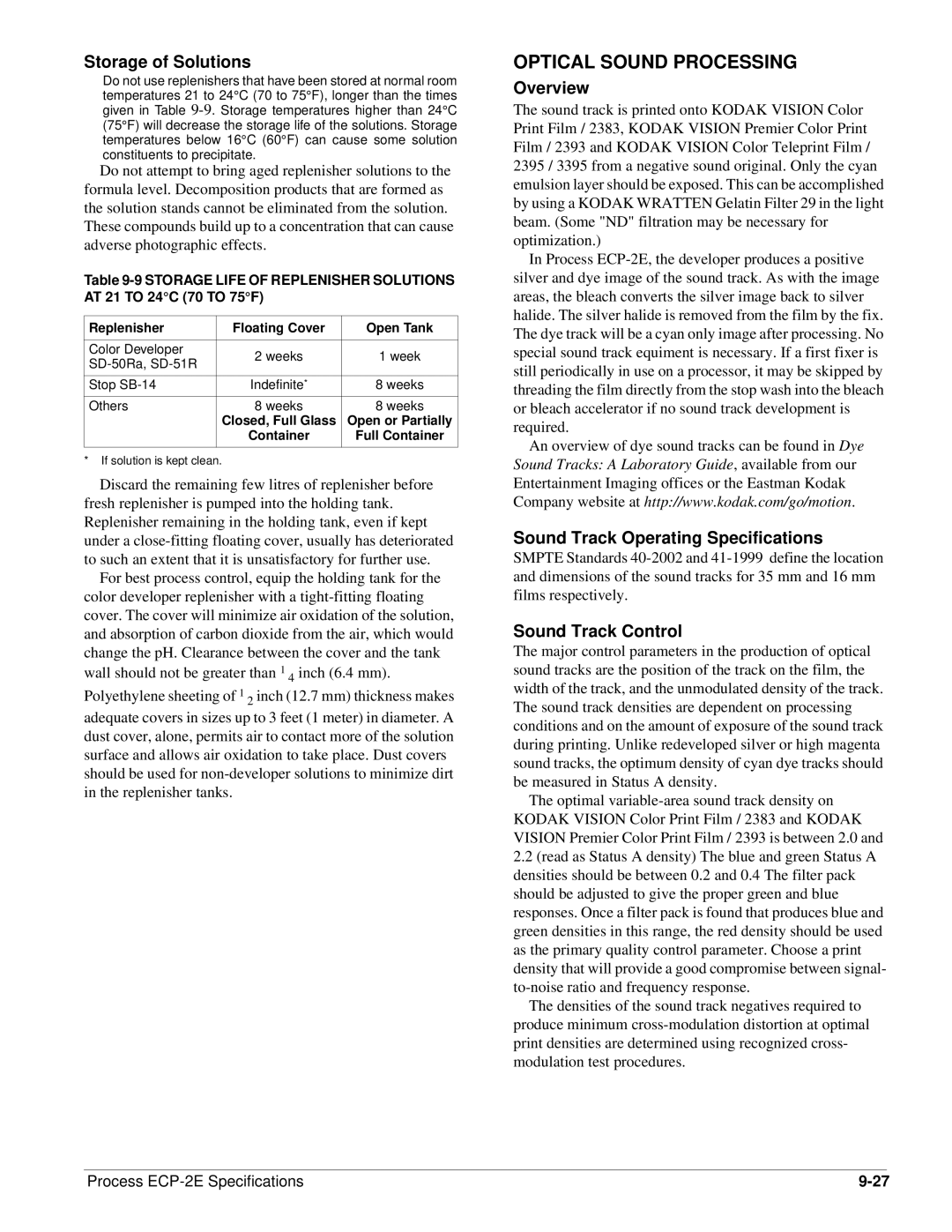
Module 9 specifications
The Kodak Module 9 is a significant advancement in the world of imaging technology, specifically designed for professionals and enthusiasts seeking high-quality photo prints and efficient workflow solutions. As part of the Kodak line of products, the Module 9 offers a combination of cutting-edge technology and user-friendly features that cater to a diverse range of photographic needs.One of the standout features of the Kodak Module 9 is its exceptional image quality. Leveraging advanced color science and innovative printing technologies, it produces vibrant and accurate color reproductions, ensuring that every detail of an image is captured and presented in its true form. This is particularly beneficial for photographers who require precise color representation, such as those working in fashion, product photography, or art reproduction.
The Kodak Module 9 is built with a high-performance print engine that supports various media types and sizes. This versatility allows for printing on everything from glossy photographic paper to fine art textures, enabling users to experiment with different materials to achieve their desired aesthetic. Additionally, the device is capable of producing large format prints, making it an ideal choice for those who need expansive visuals for exhibitions or displays.
Incorporating advanced connectivity options, the Module 9 ensures a seamless integration into modern workflows. It features Wi-Fi, USB, and Ethernet connectivity, which facilitates easy printing from multiple devices, whether it’s a camera, laptop, or mobile device. This flexibility is crucial for busy professionals who require quick turnaround times without compromising on quality.
One of the defining characteristics of the Kodak Module 9 is its user-friendly interface. The intuitive touchscreen display simplifies navigation, allowing users to easily adjust settings, select print modes, and monitor printing progress. This ease of use reduces the learning curve for new users, making it accessible to a wider audience.
In terms of sustainability, Kodak has incorporated environmentally friendly practices in the Module 9’s manufacturing and operation. The device supports energy-efficient modes and uses ink cartridges designed to minimize waste, aligning with the growing emphasis on sustainability in photography.
In conclusion, the Kodak Module 9 represents a forward-thinking solution in the photography and printing landscape. With its remarkable image quality, versatile media handling, robust connectivity, and user-oriented design, it stands out as a powerful tool for professionals aiming to elevate their imaging projects while maintaining an efficient and eco-friendly workflow.
