Power failure protection switch
Power failure shut off: >3 mA
General data
Measurements (without vehicle plug)
(L x B x H): | 155 x 128 x 58 mm |
Weight (without cable): | 865 g approx. |
Operating temperature: | 0...62 °C |
Operational humidity: | 0 - 80 % |
(relative humidity no condensation)
Subject to technical changes.
Operating Elements
APower inverter: q Fan (on the rear panel)
w Operation LED/Overload indicator e On/Off switch
r AC socket
t 12 V connections
bCable with connection terminals
cCable with 12 V vehicle plug
D30 A automotive flat fuse
Initial operation
Unpacking
1.Remove the device from the packaging.
2.Remove all foils.
![]() Warning:
Warning:
Do not permit small children to play with pla- stic packaging.
There is a risk of suffocation!
Check the items supplied
Before putting the device into use check to ensure that all of the items listed are present and that there are no visible signs of damage.
-Power inverter
-1 Cable with connection terminals red/black
-1 Cable with 12 V vehicle plug
-1 30 A automotive flat fuse
-This operating manual
Operational information
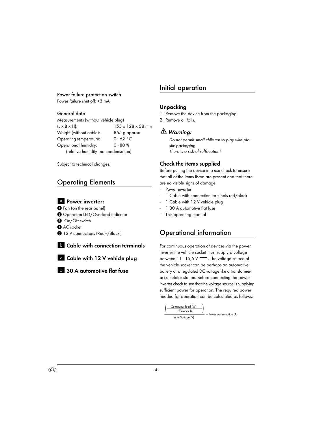
For continuous operation of devices via the power inverter the vehicle socket must supply a voltage
between 11 - 15,5 V ![]() . The voltage source of the vehicle socket can be perhaps an automotive battery or a regulated DC voltage like a transformer- accumulator station. Before connecting the power inverter check to see that the voltage source is supplying sufficient power for operation. The required power needed for operation can be calculated as follows:
. The voltage source of the vehicle socket can be perhaps an automotive battery or a regulated DC voltage like a transformer- accumulator station. Before connecting the power inverter check to see that the voltage source is supplying sufficient power for operation. The required power needed for operation can be calculated as follows:
- 4 -
