The Virtual Device – an Application Example
3.2Hardware Setup
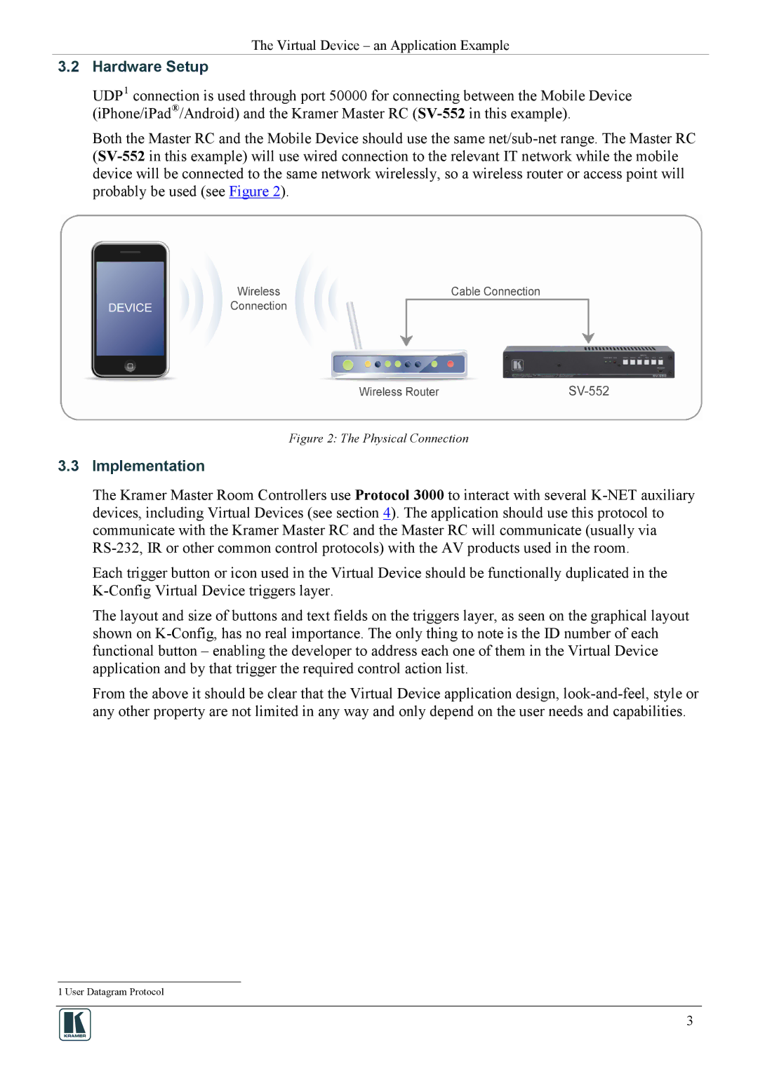
UDP1 connection is used through port 50000 for connecting between the Mobile Device (iPhone/iPad®/Android) and the Kramer Master RC (SV-552in this example).
Both the Master RC and the Mobile Device should use the same net/sub-net range. The Master RC (SV-552in this example) will use wired connection to the relevant IT network while the mobile device will be connected to the same network wirelessly, so a wireless router or access point will probably be used (see Figure 2).
Figure 2: The Physical Connection
3.3Implementation
The Kramer Master Room Controllers use Protocol 3000 to interact with several K-NET auxiliary devices, including Virtual Devices (see section 4). The application should use this protocol to communicate with the Kramer Master RC and the Master RC will communicate (usually via RS-232, IR or other common control protocols) with the AV products used in the room.
Each trigger button or icon used in the Virtual Device should be functionally duplicated in the K-Config Virtual Device triggers layer.
The layout and size of buttons and text fields on the triggers layer, as seen on the graphical layout shown on K-Config, has no real importance. The only thing to note is the ID number of each functional button – enabling the developer to address each one of them in the Virtual Device application and by that trigger the required control action list.
From the above it should be clear that the Virtual Device application design, look-and-feel, style or any other property are not limited in any way and only depend on the user needs and capabilities.
1 User Datagram Protocol
3