The Virtual Device – an Application Example
3.3.1A Setup Example
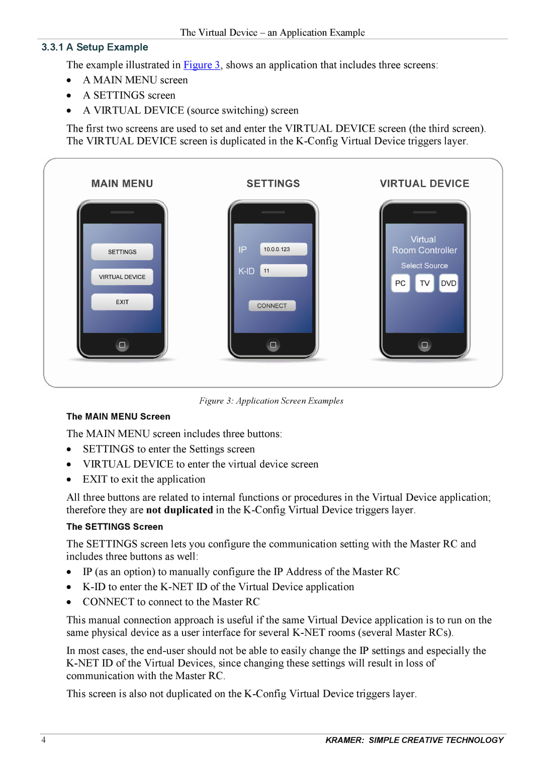
The example illustrated in Figure 3, shows an application that includes three screens:
•A MAIN MENU screen
•A SETTINGS screen
•A VIRTUAL DEVICE (source switching) screen
The first two screens are used to set and enter the VIRTUAL DEVICE screen (the third screen). The VIRTUAL DEVICE screen is duplicated in the
Figure 3: Application Screen Examples
The MAIN MENU Screen
The MAIN MENU screen includes three buttons:
•SETTINGS to enter the Settings screen
•VIRTUAL DEVICE to enter the virtual device screen
•EXIT to exit the application
All three buttons are related to internal functions or procedures in the Virtual Device application; therefore they are not duplicated in the
The SETTINGS Screen
The SETTINGS screen lets you configure the communication setting with the Master RC and includes three buttons as well:
•IP (as an option) to manually configure the IP Address of the Master RC
•
•CONNECT to connect to the Master RC
This manual connection approach is useful if the same Virtual Device application is to run on the same physical device as a user interface for several
In most cases, the
This screen is also not duplicated on the
4 | KRAMER: SIMPLE CREATIVE TECHNOLOGY |