Your
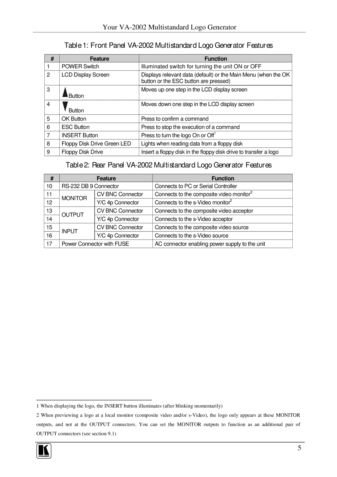
Table 1: Front Panel VA-2002 Multistandard Logo Generator Features
# |
|
|
| Feature |
| Function | |
1 |
| POWER Switch | Illuminated switch for turning the unit ON or OFF | ||||
2 |
| LCD Display Screen | Displays relevant data (default) or the Main Menu (when the OK | ||||
|
|
|
|
|
| button or the ESC button are pressed) | |
3 |
|
| Button |
|
| Moves up one step in the LCD display screen | |
|
|
|
|
|
|
| |
4 |
|
| Button |
|
| Moves down one step in the LCD display screen | |
|
|
|
|
|
|
| |
5 |
| OK Button |
|
| Press to confirm a command | ||
6 |
| ESC Button |
|
| Press to stop the execution of a command | ||
7 |
| INSERT Button | Press to turn the logo On or Off1 | ||||
8 |
| Floppy Disk Drive Green LED | Lights when reading data from a floppy disk | ||||
9 |
| Floppy Disk Drive | Insert a floppy disk in the floppy disk drive to transfer a logo | ||||
|
|
| Table 2: Rear Panel | ||||
|
|
|
|
|
|
|
|
# |
|
|
|
| Feature |
| Function |
10 |
|
| Connects to PC or Serial Controller | ||||
11 |
| MONITOR |
| CV BNC Connector | Connects to the composite video monitor2 | ||
12 |
|
| Y/C 4p Connector |
| Connects to the | ||
|
|
|
|
| |||
13 |
| OUTPUT |
| CV BNC Connector | Connects to the composite video acceptor | ||
14 |
|
| Y/C 4p Connector |
| Connects to the | ||
|
|
|
|
| |||
15 |
| INPUT |
| CV BNC Connector | Connects to the composite video source | ||
16 |
|
| Y/C 4p Connector |
| Connects to the | ||
|
|
|
|
| |||
17 |
| Power Connector with FUSE |
| AC connector enabling power supply to the unit | |||
1 When displaying the logo, the INSERT button illuminates (after blinking momentarily)
2 When previewing a logo at a local monitor (composite video and/or
5
