VP-128H specifications
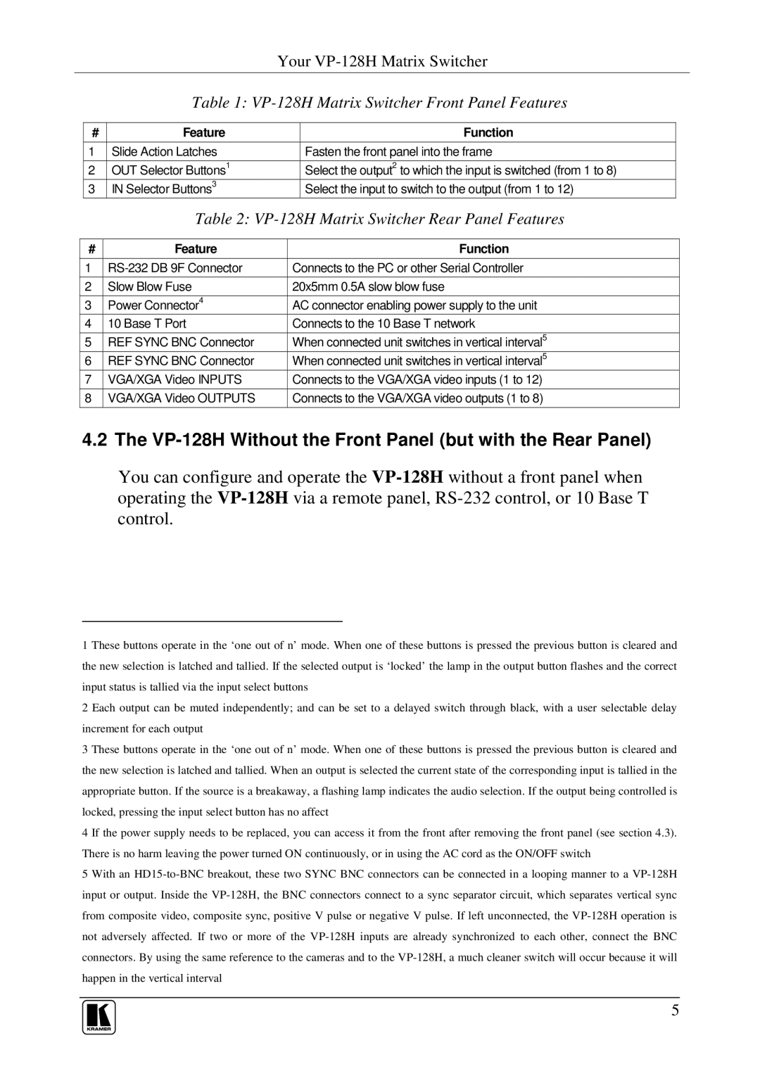
Kramer Electronics VP-128H is an advanced video processor designed to meet the demands of professional AV applications. It excels in delivering high-quality video and audio signals with versatility and efficiency. The VP-128H is particularly ideal for locations that require multi-screen setups such as control rooms, corporate presentations, and large venues.One of the standout features of the VP-128H is its ability to handle video resolution up to 4K at 60Hz. This ensures that users can enjoy crisp and clear imagery, making it suitable for high-resolution content and detailed visuals. The unit supports a wide range of video formats including HDMI, which allows for seamless integration with modern audio-visual systems.
The VP-128H utilizes advanced scaling technology that upscales lower-resolution sources to match the output display’s resolution. This feature is especially beneficial in environments where various source materials are used, ensuring that the visual quality remains consistent and impressive across all platforms. Additionally, the processor incorporates a powerful video processing engine, enabling real-time control of various video parameters such as brightness, contrast, and color correction.
Flexibility is another key characteristic of the VP-128H. It boasts multiple input options, allowing users to connect multiple sources without hassle. The intuitive layout makes it easy to switch between sources and manage outputs effectively. The device also supports video wall configurations, which is essential for creating stunning display environments where multiple screens are seamlessly synced.
In terms of connectivity, the VP-128H offers both HDMI and HDBaseT options, ensuring that users can effectively transmit high-definition content over long distances without signal degradation. The HDBaseT technology is particularly noteworthy as it allows for the extension of 4K video, audio, Ethernet, and control signals over a single CAT5e/6 cable, providing a streamlined installation process.
The user-friendly design includes an intuitive web-based interface, making it straightforward to configure settings and monitor performance remotely. This is a significant advantage for system integrators and operators who require quick adjustments without the hassle of navigating through complex menus.
With robust build quality and reliability, Kramer Electronics VP-128H is designed to withstand the demands of high-usage environments. It’s a versatile solution suitable for a range of professional applications, ensuring that users achieve optimal audio-visual performance consistently. Whether in corporate settings, educational institutions, or events, the VP-128H delivers exceptional quality and flexibility.

