CONVERSIONS
12) REPLACING NOZZLES
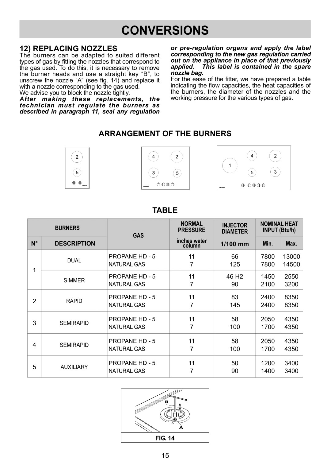
The burners can be adapted to suited different types of gas by fitting the nozzles that correspond to the gas used. To do this, it is necessary to remove the burner heads and use a straight key “B”, to unscrew the nozzle “A” (see fig. 14) and replace it with a nozzle corresponding to the gas used.
We advise you to block the nozzle tightly.
After making these replacements, the technician must regulate the burners as described in paragraph 11, seal any regulation
or
For the ease of the fitter, we have prepared a table indicating the flow capacities, the heat capacities of the burners, the diameter of the nozzles and the working pressure for the various types of gas.
ARRANGEMENT OF THE BURNERS
TABLE
|
|
|
|
|
|
| |
| BURNERS |
| NORMAL | INJECTOR | NOMINALHEAT | ||
| GAS | PRESSURE | DIAMETER | INPUT(Btu/h) | |||
N° | DESCRIPTION | incheswater | 1/100 mm | Min. | Max. | ||
| |||||||
| column | ||||||
| DUAL | PROPANE HD | 11 | 66 | 7800 | 13000 | |
1 | NATURALGAS | 7 | 125 | 7800 | 14500 | ||
| |||||||
SIMMER | PROPANE HD | 11 | 46 H2 | 1450 | 2550 | ||
| |||||||
| NATURALGAS | 7 | 90 | 2100 | 3200 | ||
|
| ||||||
2 | RAPID | PROPANE HD | 11 | 83 | 2400 | 8350 | |
NATURALGAS | 7 | 145 | 2400 | 8350 | |||
|
| ||||||
3 | SEMIRAPID | PROPANE HD | 11 | 58 | 2050 | 4350 | |
NATURALGAS | 7 | 100 | 1700 | 4350 | |||
|
| ||||||
4 | SEMIRAPID | PROPANE HD | 11 | 58 | 2050 | 4350 | |
NATURALGAS | 7 | 100 | 1700 | 4350 | |||
|
| ||||||
5 | AUXILIARY | PROPANE HD | 11 | 50 | 1200 | 3400 | |
NATURALGAS | 7 | 90 | 1400 | 3400 | |||
|
| ||||||
FIG. 14
15