WS-2510 specifications
The La Crosse Technology WS-2510 is a versatile weather station designed for those who want to keep an eye on environmental conditions from the comfort of their own homes. With its sleek design and user-friendly interface, the WS-2510 provides a wealth of data about local weather conditions at a glance.One of the primary features of the WS-2510 is its accurate and reliable weather monitoring capabilities. The station measures indoor and outdoor temperatures, humidity levels, wind speed, and rainfall. This comprehensive monitoring system allows users to gain valuable insights into current weather patterns, making it easier to plan outdoor activities or simply understand changing climatic conditions.
Equipped with wireless technology, the WS-2510 transmits data from the outdoor sensor to the indoor display unit without the need for messy cables, allowing for easy installation and positioning of the sensor. This feature enhances the convenience of real-time monitoring, as users can place the outdoor unit in the optimal location for accurate readings.
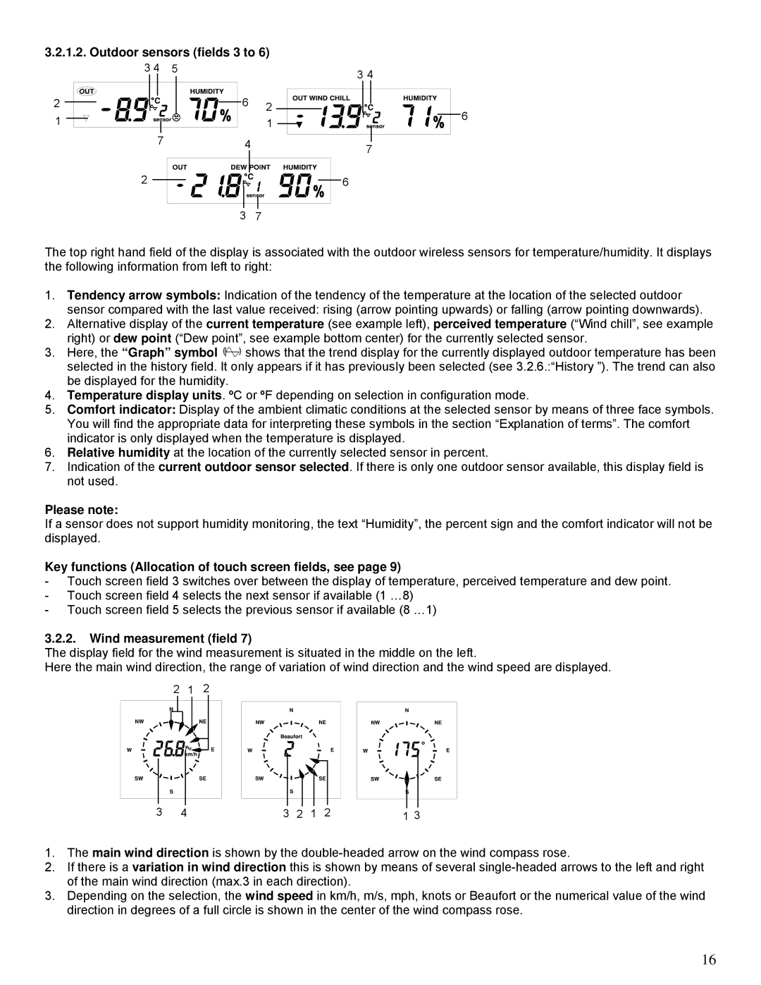
The WS-2510 is also notable for its multifunctional display. The indoor console features a large, easy-to-read LCD screen that showcases critical weather information in a clear format. Moreover, it includes trend indicators that display historical data, helping users track changes over time. The display updates frequently, ensuring that the information presented is current and useful.
In terms of technology, the WS-2510 utilizes advanced sensors for temperature, humidity, and wind measurements, ensuring high accuracy. It also uses a robust wireless communication protocol that provides a reliable connection between the outdoor and indoor units.
Another attractive feature of the WS-2510 is its ability to store data over time. Users can review past weather conditions, which is especially beneficial for those interested in tracking patterns, such as seasonal changes or anomalies. The data storage function allows for a more nuanced understanding of local climate trends.
For enthusiasts and professionals alike, the La Crosse Technology WS-2510 provides a cost-effective, reliable solution for weather monitoring. Its blend of advanced technology, user-friendly features, and sleek design makes it an appealing choice for anyone looking to bring the power of meteorological data into their home. With the WS-2510, monitoring local weather has never been easier or more engaging.

