The remote temperature sensor should be placed in a dry, shaded area. The remote temperature sensor has a range of 80 feet. Any walls that the signal will have to pass through will reduce distance. An outdoor wall or window will have 20 to 30 feet of resistance and an interior wall will have 10 to 20 feet of resistance. Your distance plus resistance should not exceed 80 ft. in a straight line.
NOTE: Fog and mist will not harm your remote temperature sensor but direct rain must be avoided.
To complete the set up of your temperature clock after the 10 minutes have passed please follow the steps below.
DETAILED
I)BATTERY INSTALLATION
Note: To avoid
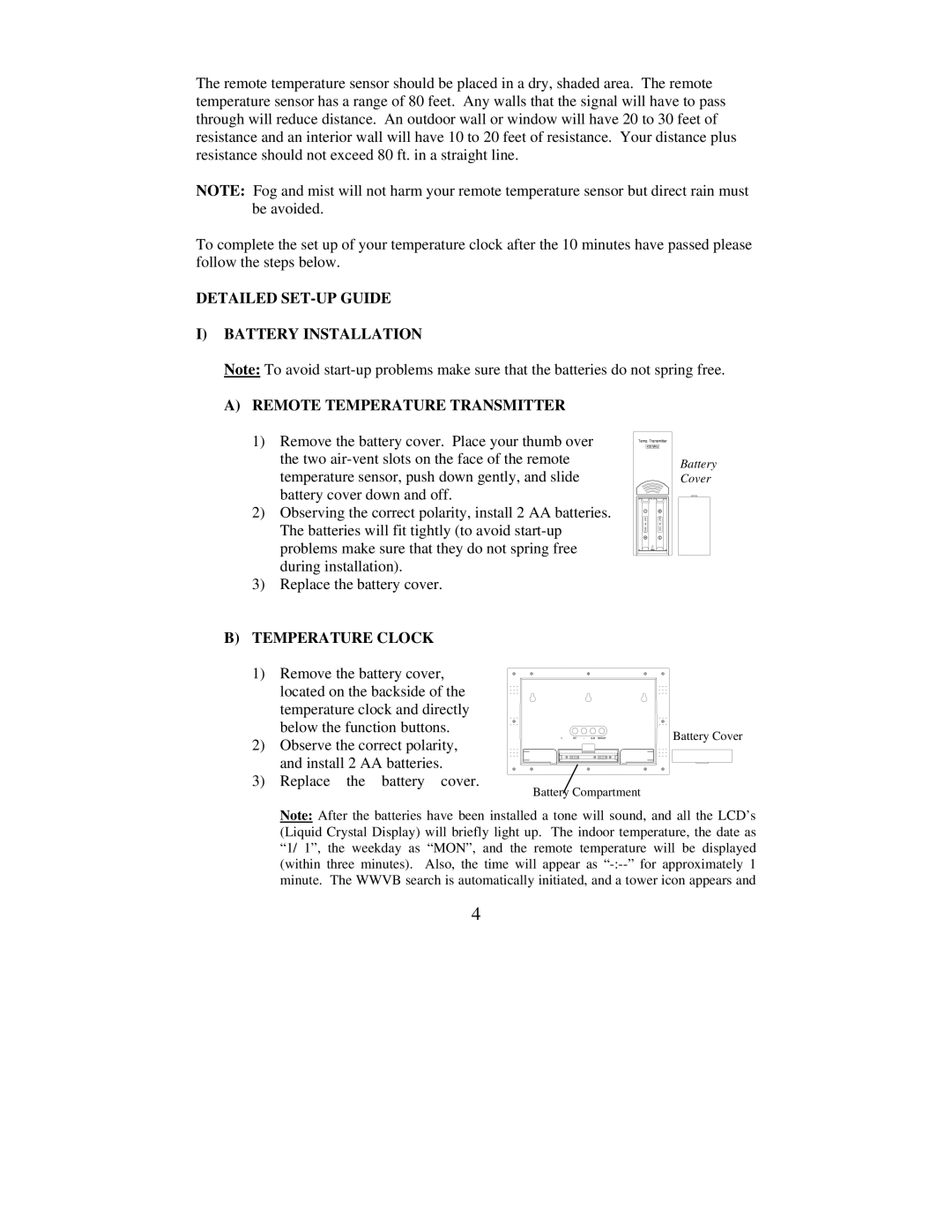
A)REMOTE TEMPERATURE TRANSMITTER
1)Remove the battery cover. Place your thumb over the two
2)Observing the correct polarity, install 2 AA batteries. The batteries will fit tightly (to avoid
3)Replace the battery cover.
Battery Cover
B)TEMPERATURE CLOCK
1)Remove the battery cover, located on the backside of the temperature clock and directly below the function buttons.
2)Observe the correct polarity, and install 2 AA batteries.
3)Replace the battery cover.
Battery Cover
Battery Compartment
Note: After the batteries have been installed a tone will sound, and all the LCD’s (Liquid Crystal Display) will briefly light up. The indoor temperature, the date as “1/ 1”, the weekday as “MON”, and the remote temperature will be displayed (within three minutes). Also, the time will appear as
4