Digital Display Wall Clock Guide | Page 10 |
Replacing an Existing DDC4 Wall Clock
When replacing an older style DDC4 Wall Clock it will be necessary to remove any connectors used by the older style clock and attach the wires to the new DDC Series Wall Clock as described above.
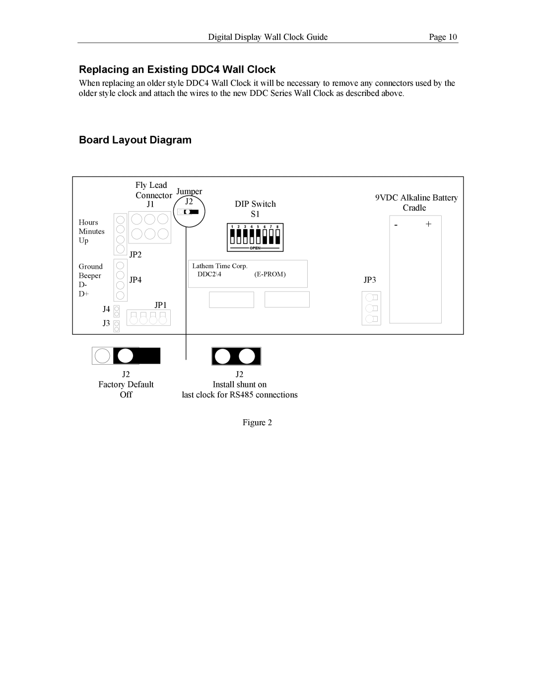
Board Layout Diagram
Fly Lead
Connector Jumper
J1 J2
Hours
Minutes
Up
Down JP2
DIP Switch
S1
1 ![]()
![]() 2
2 ![]()
![]() 3
3 ![]()
![]() 4
4 ![]()
![]() 5
5 ![]()
![]() 6
6 ![]()
![]() 7
7 ![]()
![]() 8
8
OPEN
9VDC Alkaline Battery
Cradle
-+
Ground
Beeper JP4
D-
D+
J4 JP1
J3
Lathem Time Corp. |
|
|
|
|
| ||
DDC2\4 |
| JP3 | |||||
|
|
|
|
|
|
| |
|
|
|
|
|
|
|
|
|
|
|
|
|
|
|
|
|
|
|
|
|
|
|
|
|
|
|
|
|
|
|
|
|
|
|
|
|
|
|
|
|
|
|
|
|
|
|
|
J2 | J2 |
Factory Default | Install shunt on |
Off | last clock for RS485 connections |
| Figure 2 |