DDC2 / | Digital Display Wall Clock Guide | Page 44 |
Appendix B - DDC2-RS-24 / DDC4-RS-24 Wiring
The
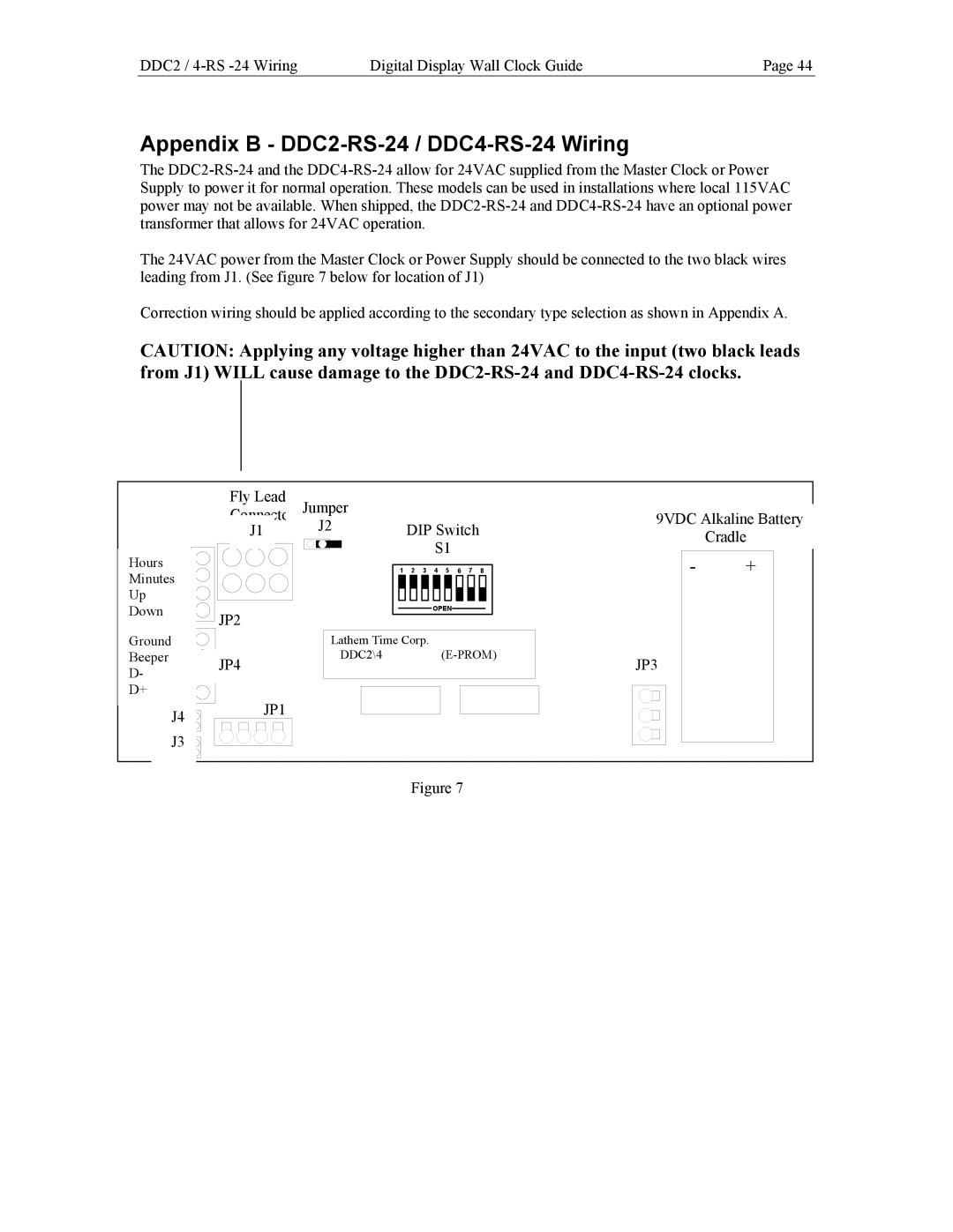
The 24VAC power from the Master Clock or Power Supply should be connected to the two black wires leading from J1. (See figure 7 below for location of J1)
Correction wiring should be applied according to the secondary type selection as shown in Appendix A.
CAUTION: Applying any voltage higher than 24VAC to the input (two black leads from J1) WILL cause damage to the
Fly Lead
Connector Jumper
J1 J2
Hours
Minutes
Up
Down JP2
DIP Switch
S1
1 ![]()
![]() 2
2 ![]()
![]() 3
3 ![]()
![]() 4
4 ![]()
![]() 5
5 ![]()
![]() 6
6 ![]()
![]() 7
7 ![]()
![]() 8
8
OPEN
9VDC Alkaline Battery
Cradle
-+
Ground
Beeper JP4
D-
D+
J4 JP1
J3
Lathem Time Corp. |
|
|
|
| |
DDC2\4 |
| JP3 | |||
|
|
|
|
| |
|
|
|
|
|
|
|
|
|
|
|
|
|
|
|
|
|
|
Figure 7