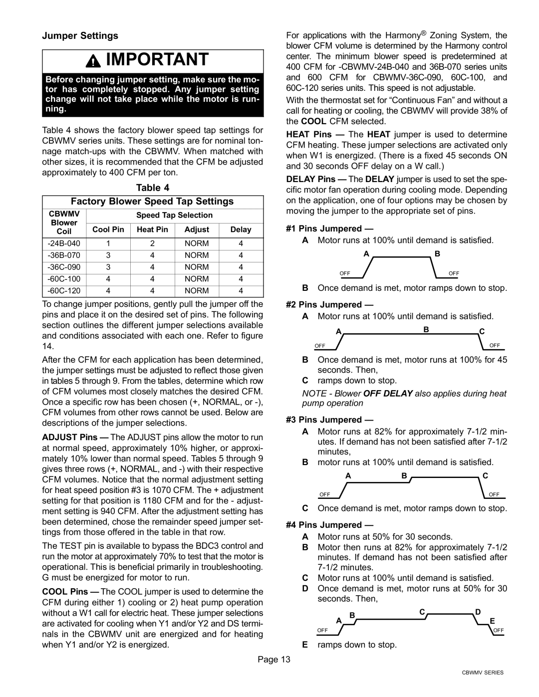
Jumper Settings

IMPORTANT

Before changing jumper setting, make sure the mo- tor has completely stopped. Any jumper setting change will not take place while the motor is run- ning.

Table 4 shows the factory blower speed tap settings for CBWMV series units. These settings are for nominal ton- nage match−ups with the CBWMV. When matched with other sizes, it is recommended that the CFM be adjusted approximately to 400 CFM per ton.

Table 4

Factory Blower Speed Tap Settings

CBWMV


Speed Tap Selection


Blower


Cool Pin

Heat Pin

Adjust

Delay

Coil


−24B−040

1

2

NORM

4


−36B−070

3

4

NORM

4


−36C−090

3

4

NORM

4


−60C−100

4

4

NORM

4


−60C−120

4

4

NORM

4


To change jumper positions, gently pull the jumper off the pins and place it on the desired set of pins. The following section outlines the different jumper selections available and conditions associated with each one. Refer to figure 14.

After the CFM for each application has been determined, the jumper settings must be adjusted to reflect those given in tables 5 through 9. From the tables, determine which row of CFM volumes most closely matches the desired CFM. Once a specific row has been chosen (+, NORMAL, or −), CFM volumes from other rows cannot be used. Below are descriptions of the jumper selections.

ADJUST Pins The ADJUST pins allow the motor to run at normal speed, approximately 10% higher, or approxi- mately 10% lower than normal speed. Tables 5 through 9 gives three rows (+, NORMAL, and −) with their respective CFM volumes. Notice that the normal adjustment setting for heat speed position #3 is 1070 CFM. The + adjustment setting for that position is 1180 CFM and for the − adjust- ment setting is 940 CFM. After the adjustment setting has been determined, chose the remainder speed jumper set- tings from those offered in the table in that row.

The TEST pin is available to bypass the BDC3 control and run the motor at approximately 70% to test that the motor is operational. This is beneficial primarily in troubleshooting. G must be energized for motor to run.

COOL Pins The COOL jumper is used to determine the CFM during either 1) cooling or 2) heat pump operation without a W1 call for electric heat. These jumper selections are activated for cooling when Y1 and/or Y2 and DS termi- nals in the CBWMV unit are energized and for heating when Y1 and/or Y2 is energized.

For applications with the Harmony® Zoning System, the blower CFM volume is determined by the Harmony control center. The minimum blower speed is predetermined at 400 CFM for −CBWMV−24B−040 and 36B−070 series units and 600 CFM for CBWMV−36C−090, 60C−100, and 60C−120 series units. This speed is not adjustable.

With the thermostat set for

call for heating or cooling, the CBWMV will provide 38% of the COOL CFM selected.

HEAT Pins The HEAT jumper is used to determine CFM heating. These jumper selections are activated only when W1 is energized. (There is a fixed 45 seconds ON and 30 seconds OFF delay on a W call.)

DELAY Pins The DELAY jumper is used to set the spe- cific motor fan operation during cooling mode. Depending on the application, one of four options may be chosen by moving the jumper to the appropriate set of pins.

#1 Pins Jumpered

AMotor runs at 100% until demand is satisfied.

AB

OFF

OFF

BOnce demand is met, motor ramps down to stop.

#2 Pins Jumpered

AMotor runs at 100% until demand is satisfied.

A

B

C


OFF


OFF

BOnce demand is met, motor runs at 100% for 45 seconds. Then,

Cramps down to stop.

NOTE − Blower OFF DELAY also applies during heat pump operation

#3 Pins Jumpered

AMotor runs at 82% for approximately 7−1/2 min- utes. If demand has not been satisfied after 7−1/2 minutes,

Bmotor runs at 100% until demand is satisfied.

A

B

C

OFF


OFF

COnce demand is met, motor ramps down to stop.

#4 Pins Jumpered

AMotor runs at 50% for 30 seconds.

BMotor then runs at 82% for approximately 7−1/2 minutes. If demand has not been satisfied after 7−1/2 minutes.

CMotor runs at 100% until demand is satisfied.

DOnce demand is met, motor runs at 50% for 30 seconds. Then,

A B

C

D


E

OFF


OFF

Eramps down to stop.

Page 13

CBWMV SERIES

Page 13
Image 13
Lennox International Inc CBWMV, AIR HANDLERS installation instructions Jumper Settings, Factory Blower Speed Tap Settings

CBWMV, AIR HANDLERS specifications

Lennox International Inc is a renowned leader in the heating, ventilation, and air conditioning (HVAC) industry, known for its commitment to innovation and energy efficiency. Among its impressive lineup of products, the CBWMV air handlers stand out as a reliable solution for optimal indoor climate control.

The CBWMV air handler is designed to provide efficient and effective airflow while being easy to install and maintain. One of the key features of the CBWMV model is its variable speed blower motor, which allows for precise control of airflow and temperature. This innovation not only enhances comfort levels within a space but also contributes to significant energy savings. By adjusting the speed of the motor according to the heating or cooling demand, the system operates more efficiently, reducing energy usage by up to 40% compared to conventional systems.

Another important characteristic of the CBWMV air handlers is their compatibility with a range of heating and cooling systems, including heat pumps and gas furnaces. This versatility makes them an ideal choice for residential and commercial applications alike. The unit’s compact design allows for flexible installation options, accommodating various spaces without compromising performance.

The CBWMV series is also engineered to provide superior air quality. With advanced filtration options, these air handlers can effectively remove dust, allergens, and pollutants from the air, promoting a healthier indoor environment. Many models come equipped with a MERV 16 filter, enhancing the filtration capability, and ensuring that occupants breathe cleaner air.

Durability is another hallmark of the CBWMV line. Constructed with high-quality materials, these air handlers can withstand rigorous use and environmental conditions. The units are designed to require minimal maintenance, with features that facilitate easy access for filter changes and routine servicing.

Additionally, the CBWMV series integrates seamlessly with Lennox’s smart technology solutions, allowing users to monitor and control their HVAC systems remotely. The compatibility with home automation systems ensures that users can optimize comfort settings and efficiency with ease.

In conclusion, Lennox International Inc's CBWMV air handlers offer a remarkable blend of efficiency, comfort, and innovative technology. With features that prioritize energy savings, air quality, versatility, and durability, they represent a forward-thinking choice for modern HVAC needs. Whether for residential or commercial use, these air handlers stand as a testament to Lennox's commitment to excellence in indoor climate management.