CBWMV, AIR HANDLERS specifications
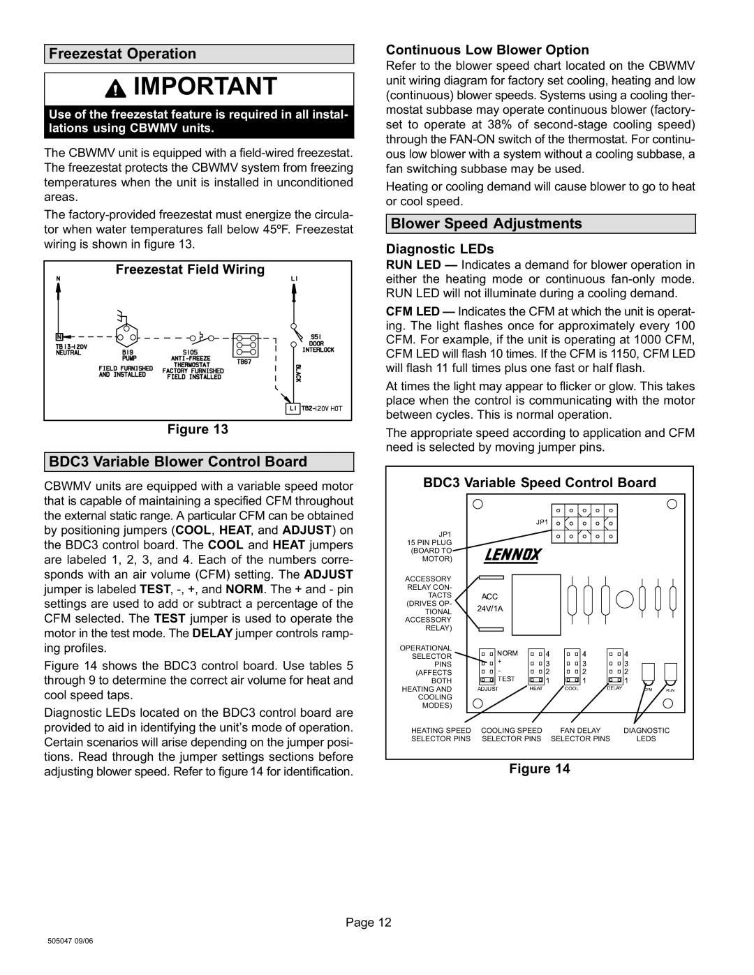
Lennox International Inc is a renowned leader in the heating, ventilation, and air conditioning (HVAC) industry, known for its commitment to innovation and energy efficiency. Among its impressive lineup of products, the CBWMV air handlers stand out as a reliable solution for optimal indoor climate control.The CBWMV air handler is designed to provide efficient and effective airflow while being easy to install and maintain. One of the key features of the CBWMV model is its variable speed blower motor, which allows for precise control of airflow and temperature. This innovation not only enhances comfort levels within a space but also contributes to significant energy savings. By adjusting the speed of the motor according to the heating or cooling demand, the system operates more efficiently, reducing energy usage by up to 40% compared to conventional systems.
Another important characteristic of the CBWMV air handlers is their compatibility with a range of heating and cooling systems, including heat pumps and gas furnaces. This versatility makes them an ideal choice for residential and commercial applications alike. The unit’s compact design allows for flexible installation options, accommodating various spaces without compromising performance.
The CBWMV series is also engineered to provide superior air quality. With advanced filtration options, these air handlers can effectively remove dust, allergens, and pollutants from the air, promoting a healthier indoor environment. Many models come equipped with a MERV 16 filter, enhancing the filtration capability, and ensuring that occupants breathe cleaner air.
Durability is another hallmark of the CBWMV line. Constructed with high-quality materials, these air handlers can withstand rigorous use and environmental conditions. The units are designed to require minimal maintenance, with features that facilitate easy access for filter changes and routine servicing.
Additionally, the CBWMV series integrates seamlessly with Lennox’s smart technology solutions, allowing users to monitor and control their HVAC systems remotely. The compatibility with home automation systems ensures that users can optimize comfort settings and efficiency with ease.
In conclusion, Lennox International Inc's CBWMV air handlers offer a remarkable blend of efficiency, comfort, and innovative technology. With features that prioritize energy savings, air quality, versatility, and durability, they represent a forward-thinking choice for modern HVAC needs. Whether for residential or commercial use, these air handlers stand as a testament to Lennox's commitment to excellence in indoor climate management.

