WARNING

WARNING TO SERVICE PERSONS! Electric shock hazard. When electrical power to the internal control box components must be available for troubleshooting, a common practice is to construct a ass" of the door interlock switch. When such a by−pass is in place, a potential shock hazard is present which can cause injury or death. Make sure any door interlock switch by−pass has been removed after troubleshooting is complete and BEFORE attempting any re- pairs to the control box components!

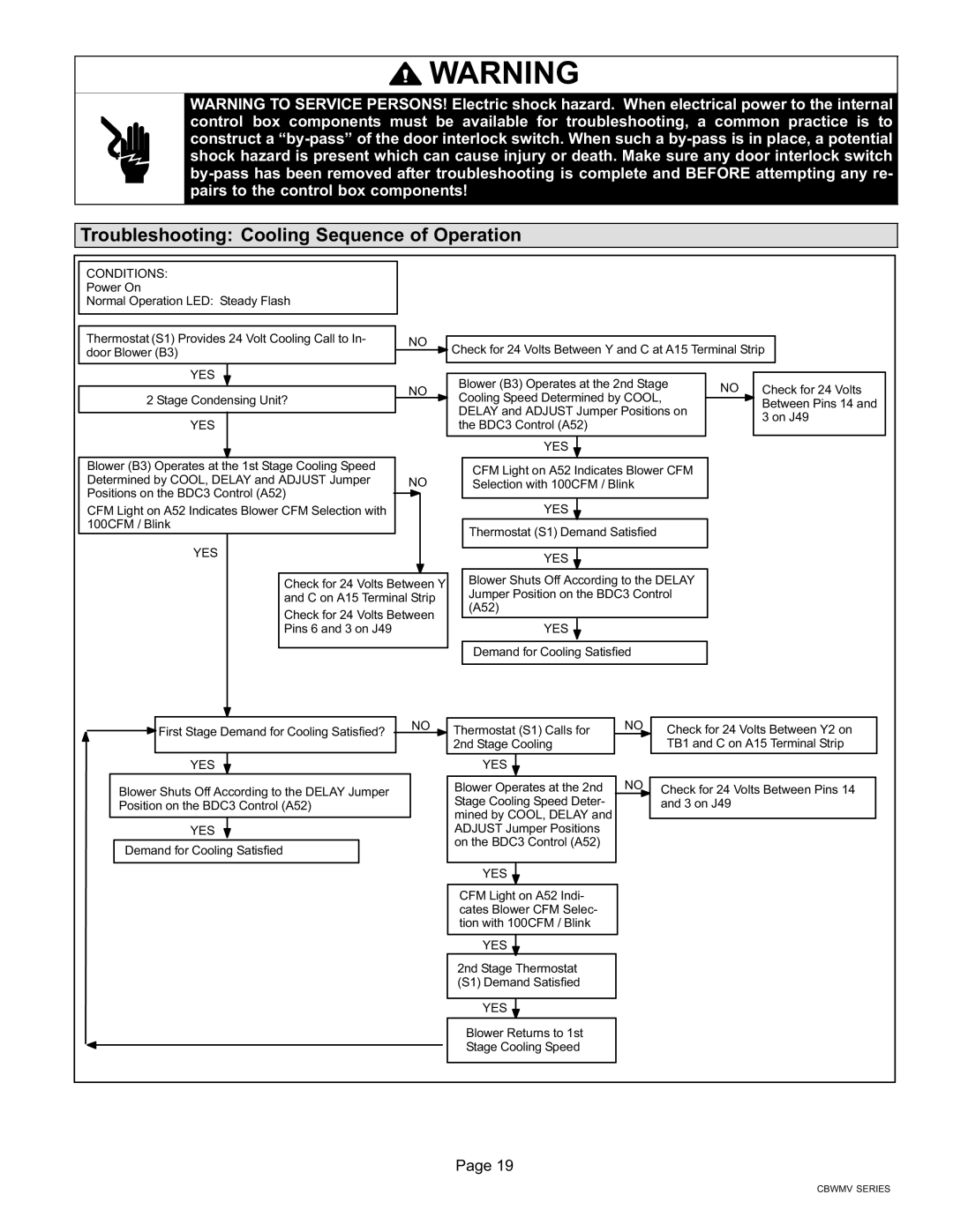
Troubleshooting: Cooling Sequence of Operation

CONDITIONS:


Power On


Normal Operation LED: Steady Flash


Thermostat (S1) Provides 24 Volt Cooling Call to In-

NO


Check for 24 Volts Between Y and C at A15 Terminal Strip

door Blower (B3)


YES


NO

Blower (B3) Operates at the 2nd Stage

NO

Check for 24 Volts


2 Stage Condensing Unit?

Cooling Speed Determined by COOL,


Between Pins 14 and


DELAY and ADJUST Jumper Positions on


YES


the BDC3 Control (A52)


3 on J49


YES


Blower (B3) Operates at the 1st Stage Cooling Speed


CFM Light on A52 Indicates Blower CFM


Determined by COOL, DELAY and ADJUST Jumper


NO


Selection with 100CFM / Blink


Positions on the BDC3 Control (A52)


CFM Light on A52 Indicates Blower CFM Selection with


YES


100CFM / Blink


Thermostat (S1) Demand Satisfied


YES


YES


Check for 24 Volts Between Y


Blower Shuts Off According to the DELAY


Jumper Position on the BDC3 Control


and C on A15 Terminal Strip


(A52)


Check for 24 Volts Between


Pins 6 and 3 on J49


YES


Demand for Cooling Satisfied


First Stage Demand for Cooling Satisfied?

YES

Blower Shuts Off According to the DELAY Jumper Position on the BDC3 Control (A52)

YES

Demand for Cooling Satisfied

NO

Thermostat (S1) Calls for


2nd Stage Cooling

YES

Blower Operates at the 2nd Stage Cooling Speed Deter- mined by COOL, DELAY and ADJUST Jumper Positions on the BDC3 Control (A52)

YES

NO

NO

Check for 24 Volts Between Y2 on TB1 and C on A15 Terminal Strip

Check for 24 Volts Between Pins 14 and 3 on J49

CFM Light on A52 Indi- cates Blower CFM Selec- tion with 100CFM / Blink

YES

2nd Stage Thermostat (S1) Demand Satisfied

YES

Blower Returns to 1st Stage Cooling Speed

Page 19

CBWMV SERIES

Page 19
Image 19
Lennox International Inc CBWMV, AIR HANDLERS installation instructions Troubleshooting Cooling Sequence of Operation

CBWMV, AIR HANDLERS specifications

Lennox International Inc is a renowned leader in the heating, ventilation, and air conditioning (HVAC) industry, known for its commitment to innovation and energy efficiency. Among its impressive lineup of products, the CBWMV air handlers stand out as a reliable solution for optimal indoor climate control.

The CBWMV air handler is designed to provide efficient and effective airflow while being easy to install and maintain. One of the key features of the CBWMV model is its variable speed blower motor, which allows for precise control of airflow and temperature. This innovation not only enhances comfort levels within a space but also contributes to significant energy savings. By adjusting the speed of the motor according to the heating or cooling demand, the system operates more efficiently, reducing energy usage by up to 40% compared to conventional systems.

Another important characteristic of the CBWMV air handlers is their compatibility with a range of heating and cooling systems, including heat pumps and gas furnaces. This versatility makes them an ideal choice for residential and commercial applications alike. The unit’s compact design allows for flexible installation options, accommodating various spaces without compromising performance.

The CBWMV series is also engineered to provide superior air quality. With advanced filtration options, these air handlers can effectively remove dust, allergens, and pollutants from the air, promoting a healthier indoor environment. Many models come equipped with a MERV 16 filter, enhancing the filtration capability, and ensuring that occupants breathe cleaner air.

Durability is another hallmark of the CBWMV line. Constructed with high-quality materials, these air handlers can withstand rigorous use and environmental conditions. The units are designed to require minimal maintenance, with features that facilitate easy access for filter changes and routine servicing.

Additionally, the CBWMV series integrates seamlessly with Lennox’s smart technology solutions, allowing users to monitor and control their HVAC systems remotely. The compatibility with home automation systems ensures that users can optimize comfort settings and efficiency with ease.

In conclusion, Lennox International Inc's CBWMV air handlers offer a remarkable blend of efficiency, comfort, and innovative technology. With features that prioritize energy savings, air quality, versatility, and durability, they represent a forward-thinking choice for modern HVAC needs. Whether for residential or commercial use, these air handlers stand as a testament to Lennox's commitment to excellence in indoor climate management.