System Operation
UNIT COMPONENTS
![]() IMPORTANT
IMPORTANT
Some scroll compressor have internal vacuum protector that will unload scrolls when suction pressure goes below 20 psig. A hissing sound will be heard when the compressor is running unloaded. Protector will reset when low pressure in system is raised above 40 psig. DO NOT REPLACE COMPRESSOR.
High Pressure Switch (S4)
14ACX units are equipped with a
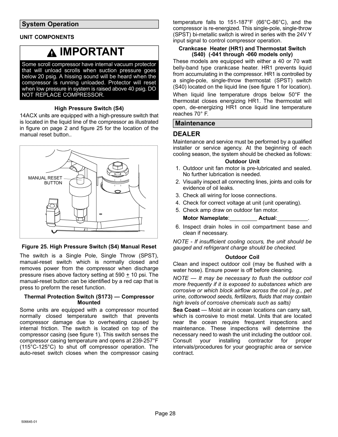
MANUAL RESET ![]()
![]()
![]()
BUTTON
Figure 25. High Pressure Switch (S4) Manual Reset
The switch is a Single Pole, Single Throw (SPST), manual−reset switch which is normally closed and removes power from the compressor when discharge pressure rises above factory setting at 590 + 10 psi. The manual−reset button can be identified by a red cap that is press to preform the reset function.
Thermal Protection Switch (S173)
Mounted
Some units are equipped with a compressor mounted normally closed temperature switch that prevents compressor damage due to overheating caused by internal friction. The switch is located on top of the compressor casing (see figure 1). This switch senses the compressor casing temperature and opens at 239−257°F (115°C−125°C) to shut off compressor operation. The auto−reset switch closes when the compressor casing
temperature falls to 151−187°F (66°C−86°C), and the compressor is re−energized. This single−pole, single−throw (SPST) bi−metallic switch is wired in series with the 24V Y input signal to control compressor operation.
Crankcase Heater (HR1) and Thermostat Switch
(S40) (−041 through −060 models only)
These models are equipped with either a 40 or 70 watt belly−band type crankcase heater. HR1 prevents liquid from accumulating in the compressor. HR1 is controlled by a single−pole, single−throw thermostat (SPST) switch (S40) located on the liquid line (see figure 1 for location).
When liquid line temperature drops below 50°F the thermostat closes energizing HR1. The thermostat will open, de−energizing HR1 once liquid line temperature reaches 70° F.
Maintenance
DEALER
Maintenance and service must be performed by a qualified installer or service agency. At the beginning of each cooling season, the system should be checked as follows:
Outdoor Unit
1.Outdoor unit fan motor is pre−lubricated and sealed. No further lubrication is needed.
2.Visually inspect all connecting lines, joints and coils for evidence of oil leaks.
3.Check all wiring for loose connections.
4.Check for correct voltage at unit (unit operating).
5.Check amp draw on outdoor fan motor.
Motor Nameplate:_________ Actual:__________.
6.Inspect drain holes in coil compartment base and clean if necessary.
NOTE - If insufficient cooling occurs, the unit should be gauged and refrigerant charge should be checked.
Outdoor Coil
Clean and inspect outdoor coil (may be flushed with a water hose). Ensure power is off before cleaning.
NOTE door coil
more frequently if it is exposed to substances which are corrosive or which block airflow across the coil (e.g., pet urine, cottonwood seeds, fertilizers, fluids that may contain high levels of corrosive chemicals such as salts)
Sea Coast
which is corrosive to most metal. Units that are located near the ocean require frequent inspections and maintenance. These inspections will determine the necessary need to wash the unit including the outdoor coil. Consult your installing contractor for proper intervals/procedures for your geographic area or service contract.
Page 28
506645−01