G61MP specifications
Lennox International Inc. has long been a leader in HVAC solutions, and the G61MP gas furnace exemplifies the company's commitment to innovation and energy efficiency. This high-efficiency gas furnace operates with an Annual Fuel Utilization Efficiency (AFUE) of up to 96%, allowing homeowners to save significantly on energy costs while maintaining a comfortable indoor environment.One of the primary features of the G61MP is its modulating gas valve. This technology enables the furnace to operate at multiple levels of heating output, ensuring that it can adjust its performance according to the home’s heating demands. By modulating the heating output, the G61MP maximizes efficiency and minimizes energy waste, providing a consistent temperature and improved comfort.
The G61MP also incorporates advanced two-stage heating, which enhances its performance by reducing temperature fluctuations in the home. This feature is especially beneficial during transitional weather periods when heating needs may vary widely. With its ability to operate on a lower stage most of the time, the furnace can produce quieter operation and reduced energy consumption.
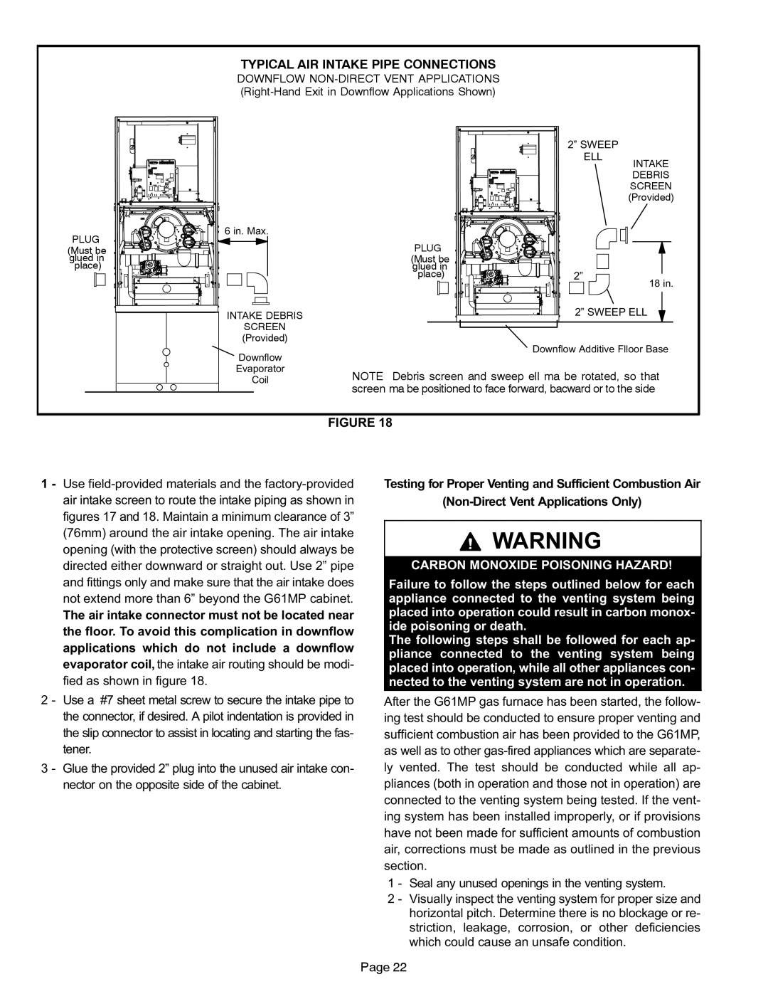
In terms of design, the G61MP includes a sealed combustion chamber that draws air from outside the home for combustion, enhancing safety and efficiency. This design feature eliminates the need for indoor air, improving indoor air quality. The furnace is also equipped with a high-efficiency ECM blower motor that not only boosts comfort but operates quietly and uses less electricity compared to traditional motors.
Further enhancing its efficiency, the G61MP utilizes a variable-speed blower, which allows for precise control of airflow throughout the home. This results in better humidity control and improved air distribution, providing an overall more comfortable environment.
The Lennox G61MP is compatible with the iComfort S30 smart thermostat, allowing homeowners to control their heating remotely, adjust settings based on their schedules, and access energy usage data. This connectivity transforms the G61MP into an integral part of a smart home ecosystem, facilitating energy conservation and comfort optimization.
Lastly, the G61MP is designed with durability in mind. Its robust construction and high-quality materials ensure reliable performance and lengthy service life. Homeowners can feel assured that they are investing in a heating solution that will meet their needs for many winters to come. In summary, the Lennox G61MP gas furnace stands out with its high efficiency, advanced technology, and user-friendly features, making it a top choice for homeowners seeking exceptional heating performance.

