Installing Contractor’s Name_______________________ | Installing Date_______________________________ |
Installing Contractor’s Phone_______________________ | Air Handler Model #___________________________ |
Job Address____________________________________ |
|
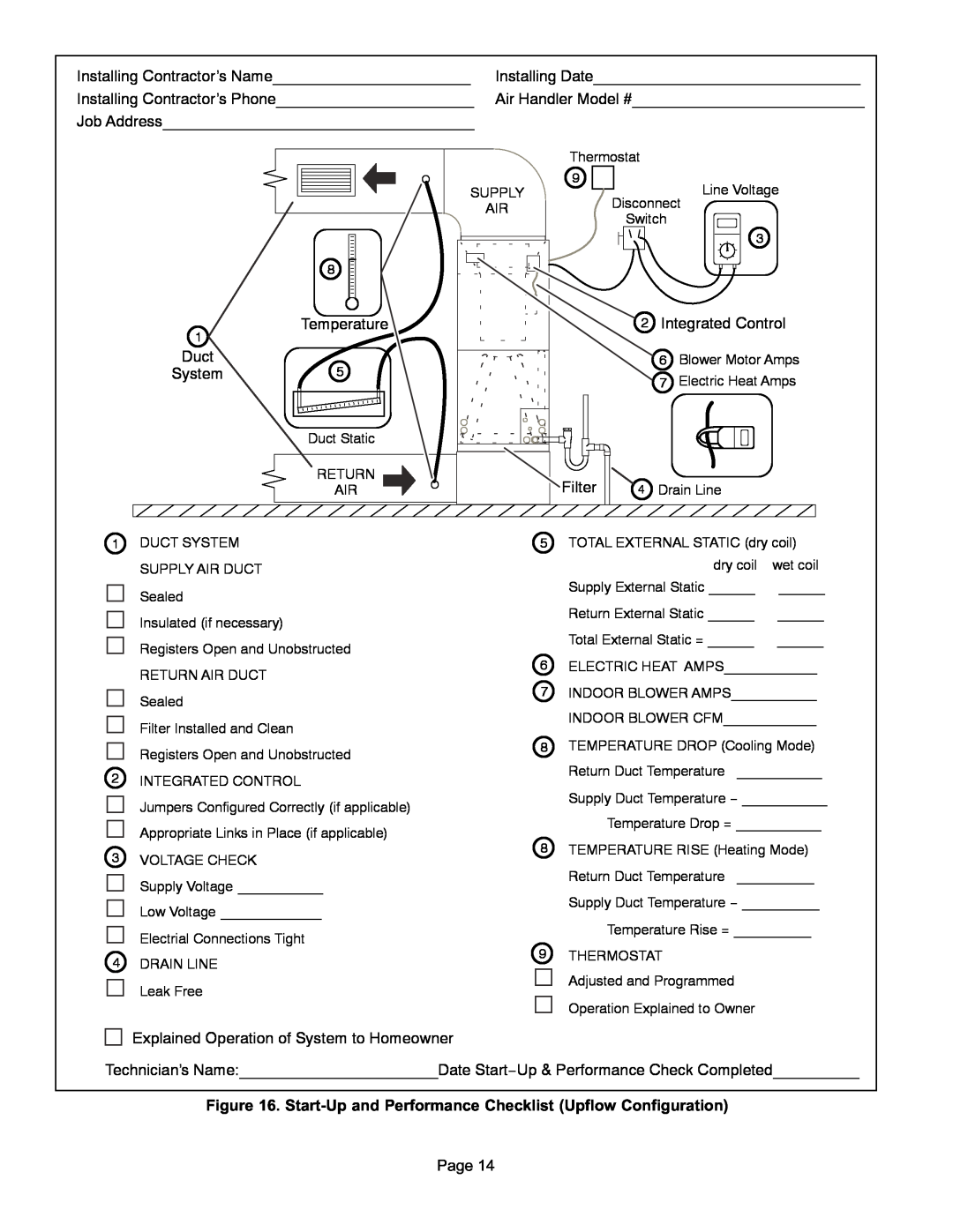
1
Duct
System
8
Temperature
5
Duct Static
RETURN
AIR
Thermostat |
|
| |
9 |
|
| Line Voltage |
SUPPLY |
|
| |
AIR | Disconnect | ||
Switch |
| ||
|
| ||
|
|
| 3 |
| 2 | Integrated Control | |
|
| 6 | Blower Motor Amps |
|
| 7 | Electric Heat Amps |
Filter | 4 | Drain Line | |
1DUCT SYSTEM SUPPLY AIR DUCT
| Sealed |
| Insulated (if necessary) |
| Registers Open and Unobstructed |
| RETURN AIR DUCT |
| Sealed |
| Filter Installed and Clean |
| Registers Open and Unobstructed |
2 | INTEGRATED CONTROL |
| Jumpers Configured Correctly (if applicable) |
| Appropriate Links in Place (if applicable) |
3 | VOLTAGE CHECK |
| Supply Voltage ___________ |
| Low Voltage _____________ |
| Electrial Connections Tight |
4DRAIN LINE ![]()
![]() Leak Free
Leak Free
5 TOTAL EXTERNAL STATIC (dry coil)
dry coil | wet coil |
Supply External Static ______ | ______ |
Return External Static ______ | ______ |
Total External Static = ______ | ______ |
6ELECTRIC HEAT AMPS____________
7INDOOR BLOWER AMPS___________
INDOOR BLOWER CFM____________
8TEMPERATURE DROP (Cooling Mode) Return Duct Temperature ___________
Supply Duct Temperature − ___________
Temperature Drop = ___________
8TEMPERATURE RISE (Heating Mode) Return Duct Temperature __________
Supply Duct Temperature − __________
Temperature Rise = __________
9 THERMOSTAT Adjusted and Programmed
Operation Explained to Owner
Explained Operation of System to Homeowner
Technician’s Name:_______________________Date Start−Up & Performance Check Completed__________
Figure 16.
Page 14