65ºF

START: Measure outdoor ambient temperature

and

ABOVE

USEDO NOTWEIGHCHARGE-IN M THODUNIT

Weigh(Results-in orofremovechargingrefrigerantat low

ABOVE or

BELOW

bas d upon line length

temperatures not reliable)

64ºF and


BELOW

APPROACH TXV

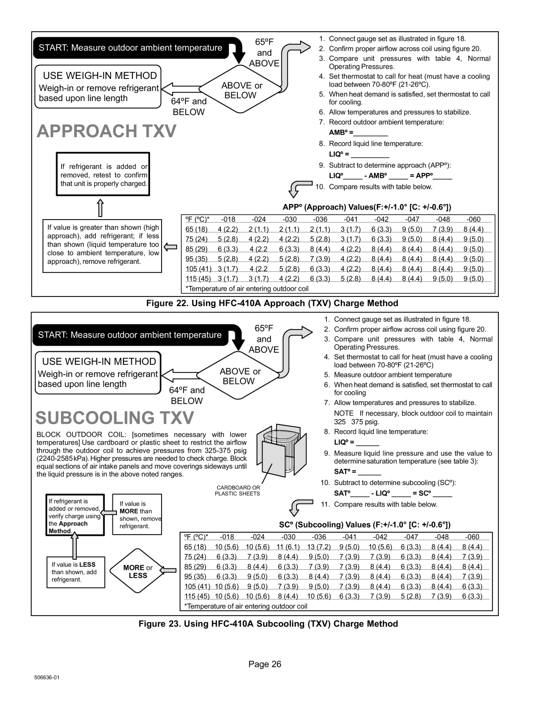
If refrigerant is added or removed, retest to confirm that unit is properly charged.

1.Connect gauge set as illustrated in figure 18.

2.Confirm proper airflow across coil using figure 20.

3.Compare unit pressures with table 4, Normal Operating Pressures.

4.Set thermostat to call for heat (must have a cooling load between 70-80ºF (21−26ºC).

5.When heat demand is satisfied, set thermostat to call for cooling.

6.Allow temperatures and pressures to stabilize.

7.Record outdoor ambient temperature: AMBº =_________

8.Record liquid line temperature: LIQº = __________

9.Subtract to determine approach (APPº): LIQº_____ − AMBº _____ = APPº_____

10.Compare results with table below.

If value is greater than shown (high approach), add refrigerant; if less than shown (liquid temperature too close to ambient temperature, low approach), remove refrigerant.

APPº (Approach) Values(F:+/−1.0° [C: +/−0.6°])

ºF (ºC)*

−018

−024

−030

−036

−041

−042

−047

−048

−060

65 (18)

4 (2.2)

2 (1.1)

2 (1.1)

2 (1.1)

3 (1.7)

6 (3.3)

9 (5.0)

7 (3.9)

8 (4.4)

75 (24)

5 (2.8)

4 (2.2)

4 (2.2)

5 (2.8)

3 (1.7)

6 (3.3)

9 (5.0)

8 (4.4)

9 (5.0)

85 (29)

6 (3.3)

4 (2.2

6 (3.3)

8 (4.4)

4 (2.2)

8 (4.4)

8 (4.4)

8 (4.4)

9 (5.0)

95 (35)

5 (2,8)

4 (2.2)

5 (2.8)

7 (3.9)

4 (2.2)

8 (4.4)

8 (4.4)

8 (4.4)

9 (5.0)

105 (41)

3 (1.7)

4 (2.2

5 (2.8)

6 (3.3)

4 (2.2)

8 (4.4)

8 (4.4)

8 (4.4)

9 (5.0)

115 (45)

3 (1.7)

3 (1.7)

4 (2.2)

6 (3.3)

5 (2.8)

8 (4.4)

8 (4.4)

9 (5.0)

9 (5.0)

*Temperature of air entering outdoor coil

Figure 22. Using HFC−410A Approach (TXV) Charge Method


1.

Connect gauge set as illustrated in figure 18.


START: Measure outdoor ambient temperature

65ºF


2.

Confirm proper airflow across coil using figure 20.


and


3.

Compare unit pressures with table 4, Normal


ABOVE


Operating Pressures.


4.

Set thermostat to call for heat (must have a cooling


USE WEIGH-IN METHOD


load between 70-80ºF (21−26ºC)


DO NOT CHARGE UNIT


ABOVE or


Weigh-in or remove refrigerant


5.

Measure outdoor ambient temperature


(Results of charging at low


BELOW


based upon line length


6.

When heat demand is satisfied, set thermostat to call


temperatures not reliable)

64ºF and


for cooling


BELOW


7.

Allow temperatures and pressures to stabilize.


SUBCOOLING TXV


NOTE − If necessary, block outdoor coil to maintain


325 − 375 psig.


BLOCK OUTDOOR COIL: [sometimes necessary with lower


8.

Record liquid line temperature:


temperatures] Use cardboard or plastic sheet to restrict the airflow


LIQº = ______


through the outdoor coil to achieve pressures from 325−375 psig


9.

Measure liquid line pressure and use the value to


(2240−2585 kPa). Higher pressures are needed to check charge. Block


determine saturation temperature (see table 3):


equal sections of air intake panels and move coverings sideways until


the liquid pressure is in the above noted ranges.


SATº = ______


CARDBOARD OR


10.

Subtract to determine subcooling (SCº):


SATº_____ − LIQº _____ = SCº _____


PLASTIC SHEETS


If refrigerant is


If value is


11.

Compare results with table below.


added or removed,


MORE than


verify charge using


shown, remove


the Approach


SCº (Subcooling) Values (F:+/−1.0° [C: +/−0.6°])


refrigerant.


Method.


ºF (ºC)*

−018

−024


−030

−036

−041

−042

−047

−048

−060


65 (18)

10 (5.6)

10 (5.6)


11 (6.1)

13 (7.2)

9 (5.0)

10 (5.6)

6 (3.3)

8 (4.4)

8 (4.4)


75 (24)

6 (3.3)

7 (3.9)


8 (4.4)


9 (5.0)

7 (3.9)

7 (3.9)

6 (3.3)

8 (4.4)

7 (3.9)


If value is LESS


MORE or


85 (29)

6 (3.3)

8 (4.4)


6 (3.3)


7 (3.9)

7 (3.9)

8 (4.4)

6 (3.3)

8 (4.4)

8 (4.4)


than shown, add


LESS


95 (35)

6 (3.3)

9 (5.0)


6 (3.3)


8 (4.4)

7 (3.9)

8 (4.4)

6 (3.3)

8 (4.4)

7 (3.9)


refrigerant.


105 (41)

10 (5.6)

9 (5.0)


7 (3.9)


9 (5.0)

7 (3.9)

8 (4.4)

6 (3.3)

8 (4.4)

6 (3.3)


115 (45)

10 (5.6)

10 (5.6)


8 (4.4)


10 (5.6)

6 (3.3)

7 (3.9)

5 (2.8)

7 (3.9)

6 (3.3)


*Temperature of air entering outdoor coil


Figure 23. Using HFC−410A Subcooling (TXV) Charge Method

Page 26

506636−01

Page 26
Image 26
Lenox XC14, Elite Series installation instructions Above, Below

Elite Series, XC14 specifications

The Lenox Elite Series XC14 is a remarkable tool designed for superior cutting performance in various applications. This saw blade stands out due to its innovative technologies and features, which cater to the needs of professionals in woodworking, metalworking, and general cutting tasks.

One of the key features of the XC14 is its carbide-tipped teeth. These teeth are engineered for longevity and efficiency, allowing for extended use without performance degradation. The unique geometry of the teeth enhances cutting speed while minimizing resistance, making it ideal for a range of materials including hardwoods, softwoods, and metals.

The blade’s construction is another significant aspect of its design. Made from high-quality steel, the XC14 ensures durability and resistance to bending or warping under stress. This robust construction contributes to the blade's overall stability, resulting in smoother cuts and reduced vibration during operation.

Another noteworthy technology embedded in the XC14 is its advanced tooth design. The combination of alternate top bevel (ATB) and flat (F) configurations allows for precision cutting and a cleaner finish. This feature is particularly beneficial when working on intricate projects that require a high level of accuracy.

To enhance performance further, the XC14 incorporates a unique thin kerf design. This design reduces the width of the cut, which not only conserves material but also requires less power from the saw. This energy efficiency translates to less wear on the saw, extending the lifecycle of both the blade and the tool itself.

The blade is also designed with heat dissipation in mind. Specially engineered cooling vents help in maintaining optimal temperature during operation. This technology reduces the risk of overheating, which can compromise the integrity of the blade and the quality of the cut.

Versatility is another standout feature of the Lenox Elite Series XC14. It is suitable for table saws, miter saws, and portable saws, making it a valuable tool for professionals and DIY enthusiasts alike. Whether tackling large construction projects, meticulous cabinetry, or small home repairs, the XC14 adapts efficiently to diverse cutting needs.

In conclusion, the Lenox Elite Series XC14 combines advanced technologies, premium materials, and thoughtful design to deliver exceptional cutting performance. Its carbide-tipped teeth, innovative geometry, stable construction, thin kerf, heat dissipation features, and versatility make it a top choice for those seeking reliable and efficient cutting solutions in various applications.