4402-001
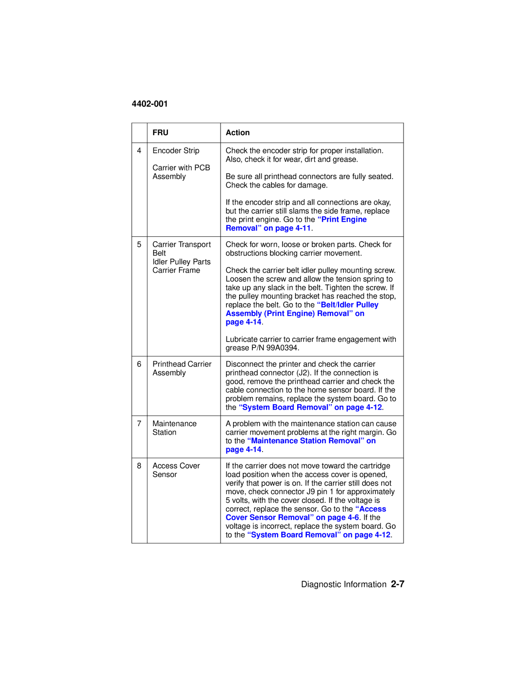
| FRU | Action |
|
|
|
4 | Encoder Strip | Check the encoder strip for proper installation. |
| Carrier with PCB | Also, check it for wear, dirt and grease. |
|
| |
| Assembly | Be sure all printhead connectors are fully seated. |
|
| Check the cables for damage. |
|
| If the encoder strip and all connections are okay, |
|
| but the carrier still slams the side frame, replace |
|
| the print engine. Go to the “Print Engine |
|
| Removal” on page |
|
|
|
5 | Carrier Transport | Check for worn, loose or broken parts. Check for |
| Belt | obstructions blocking carrier movement. |
| Idler Pulley Parts |
|
| Carrier Frame | Check the carrier belt idler pulley mounting screw. |
|
| Loosen the screw and allow the tension spring to |
|
| take up any slack in the belt. Tighten the screw. If |
|
| the pulley mounting bracket has reached the stop, |
|
| replace the belt. Go to the “Belt/Idler Pulley |
|
| Assembly (Print Engine) Removal” on |
|
| page |
|
| Lubricate carrier to carrier frame engagement with |
|
| grease P/N 99A0394. |
|
|
|
6 | Printhead Carrier | Disconnect the printer and check the carrier |
| Assembly | printhead connector (J2). If the connection is |
|
| good, remove the printhead carrier and check the |
|
| cable connection to the home sensor board. If the |
|
| problem remains, replace the system board. Go to |
|
| the “System Board Removal” on page |
|
|
|
7 | Maintenance | A problem with the maintenance station can cause |
| Station | carrier movement problems at the right margin. Go |
|
| to the “Maintenance Station Removal” on |
|
| page |
|
|
|
8 | Access Cover | If the carrier does not move toward the cartridge |
| Sensor | load position when the access cover is opened, |
|
| verify that power is on. If the carrier still does not |
|
| move, check connector J9 pin 1 for approximately |
|
| 5 volts, with the cover closed. If the voltage is |
|
| correct, replace the sensor. Go to the “Access |
|
| Cover Sensor Removal” on page |
|
| voltage is incorrect, replace the system board. Go |
|
| to the “System Board Removal” on page |
|
|
|
Diagnostic Information