Introduction
Connection Options
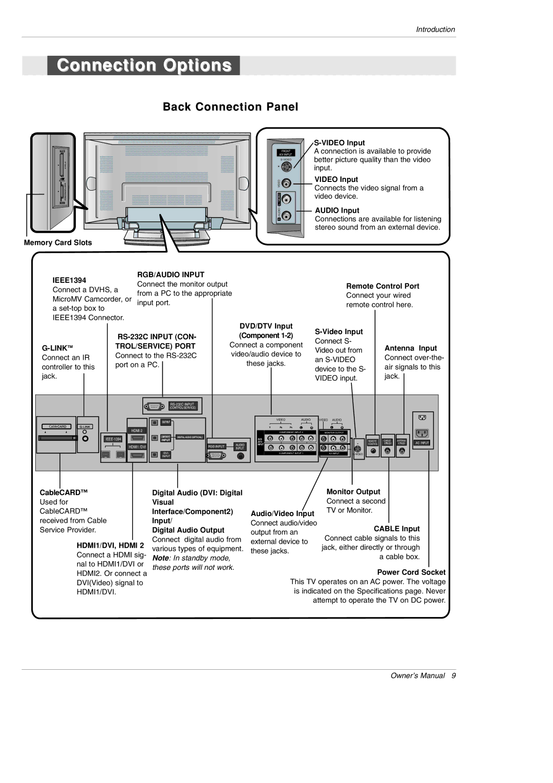
Back Connection Panel
FRONT
A/V INPUT
A connection is available to provide better picture quality than the video input.
VIDEO | VIDEO Input | |
Connects the video signal from a | ||
| ||
L / MONO | video device. | |
| ||
AUDIO | AUDIO Input | |
Connections are available for listening | ||
R |
stereo sound from an external device.
Memory Card Slots
IEEE1394 |
| RGB/AUDIO INPUT |
|
|
|
|
|
|
|
| |
| Connect the monitor output |
|
|
|
|
| Remote Control Port | ||||
Connect a DVHS, a |
|
|
|
|
| ||||||
from a PC to the appropriate |
|
|
|
| Connect your wired | ||||||
MicroMV Camcorder, or |
|
|
|
| |||||||
input port. |
|
|
|
|
|
|
| remote control here. | |||
a |
|
|
|
|
|
|
|
|
|
|
|
IEEE1394 Connector. |
|
|
| DVD/DTV Input |
|
|
|
|
| ||
|
|
|
|
|
|
|
| ||||
|
| (Component |
|
|
| ||||||
|
|
|
| Connect S- |
| ||||||
| TROL/SERVICE) PORT |
| Connect a component |
| Antenna Input | ||||||
|
| Video out from | |||||||||
Connect an IR | Connect to the |
| video/audio device to |
| an | Connect | |||||
|
| these jacks. |
|
| |||||||
controller to this | port on a PC. |
|
|
|
|
| device to the S- | air signals to this | |||
|
|
|
|
|
| ||||||
jack. |
|
|
|
|
|
|
|
| VIDEO input. | jack. | |
|
|
|
|
|
|
|
|
|
|
| |
|
| (CONTROL/SERVICE) |
|
|
|
|
|
|
|
| |
|
| OUTPUT |
|
|
| VIDEO | AUDIO |
| VIDEO AUDIO |
| |
|
|
|
|
|
|
|
|
|
|
| |
Cable |
| HDMI 2 |
|
|
|
| L | R | L | R |
|
|
|
|
|
| COMPONENT INPUT 2 |
| MONITOR OUTPUT |
| |||
|
|
|
|
|
|
|
| ||||
| COMPONENT2 | DIGITAL AUDIO (OPTICAL) |
|
| DVD |
|
|
|
|
| |
| INPUT |
|
|
|
|
|
| REMOTE | CABLE ANTENNA | ||
|
|
|
|
|
| /DTV |
|
|
| AC INPUT | |
| HDMI1 /DVI |
| RGB INPUT | AUDIO | INPUT |
|
|
| CONTROL | ||
|
|
|
|
|
|
| |||||
|
| INPUT |
|
|
| (MONO) |
|
| |||
|
|
|
|
|
|
|
|
|
| ||
|
| DVI |
|
|
| COMPONENT INPUT 1 |
| A/V INPUT |
| ||
|
| INPUT |
|
|
|
|
|
|
|
| |
|
|
|
|
|
|
|
|
|
|
| |
CableCARD™
Used for CableCARD™ received from Cable Service Provider.
HDMI1/DVI, HDMI 2
Connect a HDMI sig- nal to HDMI1/DVI or HDMI2. Or connect a DVI(Video) signal to HDMI1/DVI.
Digital Audio (DVI: Digital
Visual
Interface/Component2)
Input/
Digital Audio Output
Connect digital audio from various types of equipment. Note: In standby mode, these ports will not work.
|
| Monitor Output | |
|
| Connect a second | |
Audio/Video Input | TV or Monitor. | ||
|
| ||
Connect audio/video |
|
|
|
| CABLE Input |
| |
output from an |
|
| |
| Connect cable signals to this |
| |
external device to |
|
| |
| jack, either directly or through |
| |
these jacks. |
|
| |
| a cable box. |
| |
|
|
| |
|
|
|
|
|
| Power Cord Socket | |
This TV operates on an AC power. The voltage is indicated on the Specifications page. Never attempt to operate the TV on DC power.
Owner’s Manual 9