LG Electronics U.S.A., Inc
Plasma TV
Class B digital device
FCC Notice
Digital Cable Compatibility
TV Guide On Screen Notices for U.S.A
Important Safety Instructions
Safety Instructions
Safety Instructions
Contents
Introduction
Power Standby Indicator Program
Remote Control Sensor
Controls
Buttons
Connection Options
Channel E, D Buttons
Sensor Power Button Seen
Audio/Video Input
Memory Card Slots
Remote Control Key Functions
Mark
Installing Batteries
Installation
Installation Instructions
Accessories
60PY2DR
Grounding
Remove or Attache the Plate Cover Only 50/60PY2DR series
Arrangement wires Only 50/60PY2DR series
Swivel function
50/60PY2DR
Analog and Digital TV signals provided on cable
Analog and Digital TV signals provided on antenna
External Equipment Connections
Antenna or Cable Connection
VCR Setup
Analog and Digital TV signals provided on cable and antenna
Connection Option
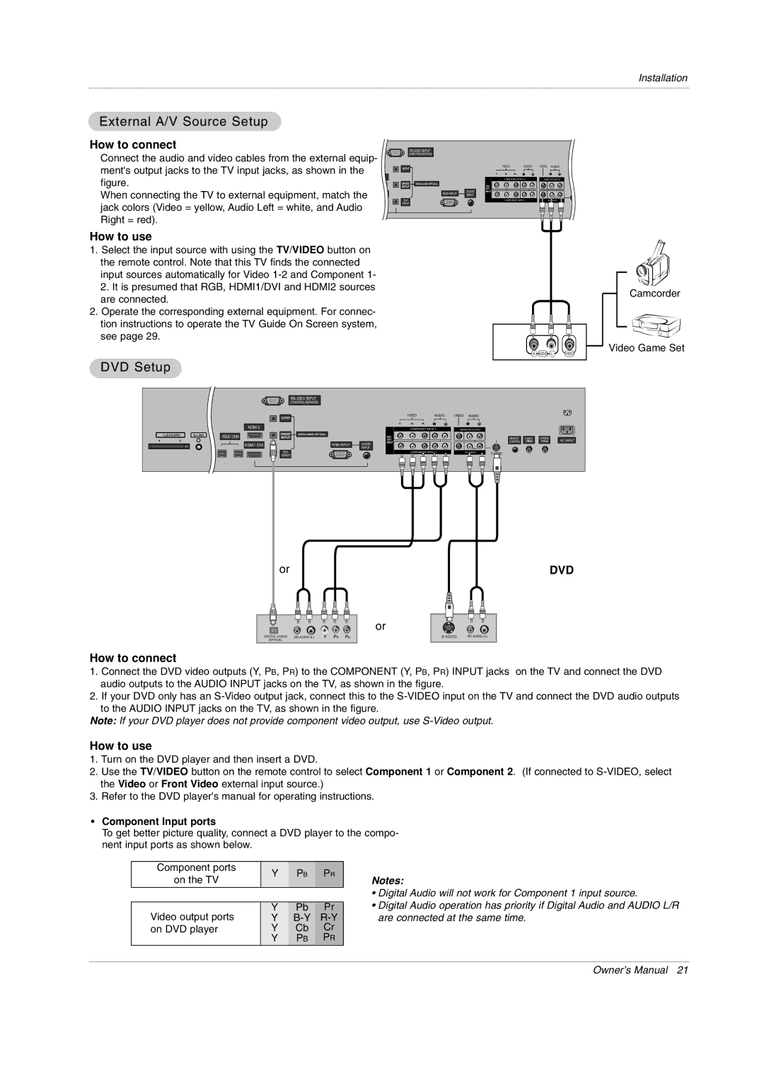
DVD Setup
External A/V Source Setup
How to connect
How to use
Hdstb Setup
CableCARDTM Setup
Or or
Digital Set-top Box
PC Setup
When the PC supports DVI How to connect
When the PC supports RGB How to connect
Monitor Display Specifications RGB-DTV
Monitor Display Specifications RGB-PC
Monitor Display Specifications HDMI-PC
Monitor Display Specifications HDMI-DTV
Digital Audio Output
Monitor Out Setup
Hdmi
Reference
Cable sample
This Mode, the Supported PC Resolution Specification
TV Guide On Screen Setup
Cable Service with a Cable Box
Cable Box Front
Screen 1 Country
TV Guide On Screen Setup
Screen 3 Do you have Cable Service connected?
Screen 2 Enter ZIP or Postal Code Option
Screen 4 Do you have a Cable Box?
Screen 7 Cable Box Configuration Diagram
Screen 6 Cable Box Tuning Channel
Make sure the G-LINKTMCable is properly installed
Screen 5 Which TV input is the cable box plugged into?
Screen 8 Cable Box Brand Name
Screen 10 Cable Box Code Testing
Screen 9 Cable Box Preparation
Screen 11 Cable Box Tuned to Channel 9?
Screen 13 Are your basic settings correct?
Screen 12 Do you have an antenna connected?
Screen 14 Congratulations
Screen 15 Helpful Information
Turning the TV On
Operation
Home Menu
On-screen Menus Language Selection
TV Setup
Setup Menu Options
EZ Scan Channel Search
Manual Scan
Channel Edit
DTV Signal Strength
Channel Label Setup
Main Picture Source Selection
Input Label
Video Reset
Color Temperature Control
Video Menu Options
EZ Picture
Audio Language
Audio Menu Options
EZ SoundRite
EZ Sound
Front Surround
Manual Sound Control Custom option
Stereo/SAP Broadcasts Setup
TV Speakers On/Off Setup
Manual Clock Setup
Auto Clock Setup
On/Off Timer Setup
For only On timer function
Auto Off
Sleep Timer
TimeShift Mode
Option Menu Features
Cinema 32 Mode Setup
Low Power
LG Logo
Aspect Ratio Control
Caption
Caption/Text
Analog Broadcasting System Captions
Caption Option
Digital Broadcasting System Captions
Front Display
ISM Image Sticking Minimization Method
Auto Demo
Chip rating and categories
Lock Menu Options
TV Rating Children
TV Rating General
Parental Lock Setup
CableCARD Function
Cable menu options
Scrambled channel
Emergency Alert Message
Cable Channel List
Recorded TV
Recorded TV
On playing the recorded program, play
Using the remote control
On playing the recorded program, edit a section
On playing the recorded program, repeat a section
What is Memory Card
Inserting a Card
How to insert and eject the Memory Card
Ejecting a card
Label-side Upward
Memory Card type
Available file in mode
Slot
Jpg Mp3
Select the Photo or Music
Photo List
Folder List
Screen Components
Photo Selection and PopUp Menu
Music List
Music title Selection and PopUp Menu
Music List
Progressing the Timeshift function
TimeShift
On progressing the Timeshift, play
Recording
Instant Record
30min 1hour 1hr 30min 2hr 2hr 30min 3hr
No Change +10min +20min +30min +40min -+50min +1hr
Watching & Record
Screen being recorded
Watch & Record Input
TV Guide On Screen system Overview
TV Guide On ScreenTM System
Screen Components
Panel Menu
Listings
Main Services
Category Search Example Movies
Search
Operation
Keyword Search
Operation
Screen a Screen B
Recordings
Operation
Schedule
Record
Remind
Change System Settings
Setup
Change Channel Display
Change Default Options
TV Guide On ScreenTM System
Cancel no icon displayed-does not record
Using the Record Button on the Remote
Record
From a Panel Menu
Manual Recording
Record Conflict
Remind
Manual Reminder
Remind Conflict
TV MicroMV Camcorder
TV Dvhs
Daisy Chain Connection
TV Dvhs + MicroMV Camcorder
Dvhs
How to play the Dvhs
JVCHM-DH5U MITSUBISHIHV-HD1000 PANASONICNV-DH2
How to play the instant reecord to the Dvhs
How to save the Dvhs to the DVR
Copy-protected contents couldn’t save to the Dvhs
WV How to save the DVR to the Dvhs
MicroMV Camcorder
WV How to play the MicroMV Camcorder
Sony DCR IP-1 Sony DCR IP-5 Sony DCR IP-45 Sony DCR IP-210
WV How to save the MicroMV Camcorder to the DVR
Operation
Loop Connection
WV Don’t connect
Watching PIP/POP/Twin Picture
Selecting an Input Signal Source for PIP/Twin Picture
Swapping the PIP/Twin Picture
TV Program selection for PIP
Adjusting Main and Sub Picture Sizes for Twin Picture
Moving the PIP sub picture
POP Picture-out-of-Picture Channel Scan
APM Adaptive Picture Mode
Brief Info
EZ Mute
Operation
Adjustment for screen Position, Size, Phase, Reset
RS-232C Setup
External Control Device Setup
Type of Connector D-Sub 9-Pin Male
RS-232C Configurations
Set ID
Command Reference List
Communication Parameters
Transmission / Receiving Protocol
Input Select Command2b Main Picture Input
Power Command2a
Screen Mute Command2d
Volume Mute Command2e
Tint Command2j
Color Command2i
Sharpness Command2k
OSD Select Command2l
PIP Input Select Command2y
Color Temperature Command2u
ISM Method/Orbiter Command2p
Low Power Command2q
Key Command m c
Channel Add/Del Command m b
Input selectCommand x b Main Picture Input
PIP Input SelectCommand x y
How to Connect
Remote Control IR Codes
IR Codes
Video
Code Hexa Function
Programming the Remote
Programming a code into a remote mode
VCRs
Programming Codes
Audio
Hdstb
Troubleshooting Checklist
Cleaning the Screen
Maintenance
Cleaning the Cabinet
Extended Absence
Models 50PY2DR-UA 60PY2DR-UA 50PX4DR-UA
Product Specifications
LG ELECTRONICS, INC Plasma TV U.S. Limited Warranty
No 3828VA0528A e 3828VB0002M
This Limited Warranty does not Apply to