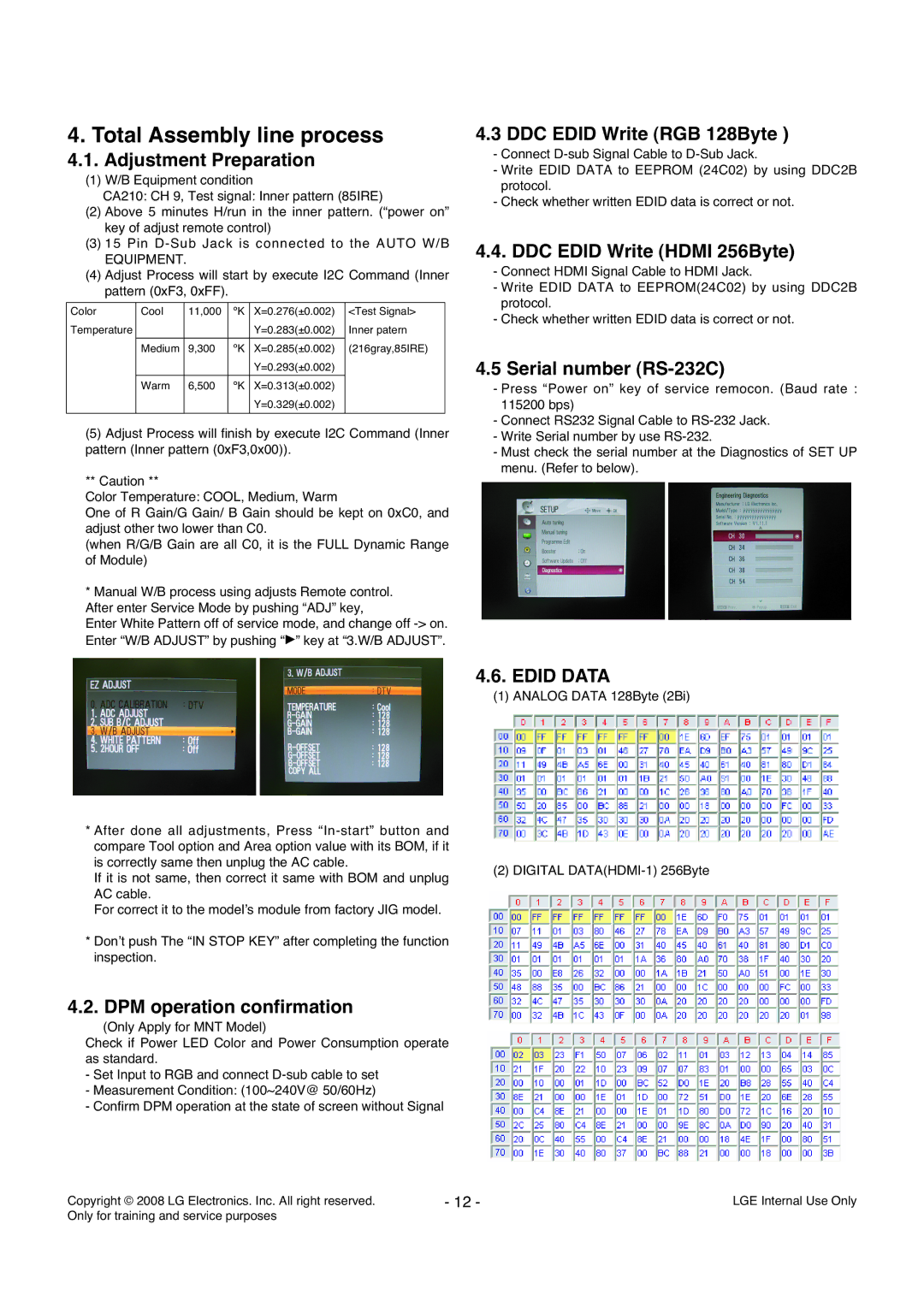
4. Total Assembly line process
4.1.Adjustment Preparation
(1)W/B Equipment condition
CA210: CH 9, Test signal: Inner pattern (85IRE)
(2)Above 5 minutes H/run in the inner pattern. (“power on” key of adjust remote control)
(3)15 Pin
EQUIPMENT.
(4)Adjust Process will start by execute I2C Command (Inner pattern (0xF3, 0xFF).
Color | Cool | 11,000 | ºK | X=0.276(±0.002) | <Test Signal> |
Temperature |
|
|
| Y=0.283(±0.002) | Inner patern |
|
|
|
|
|
|
| Medium | 9,300 | ºK | X=0.285(±0.002) | (216gray,85IRE) |
|
|
|
| Y=0.293(±0.002) |
|
|
|
|
|
|
|
| Warm | 6,500 | ºK | X=0.313(±0.002) |
|
|
|
|
| Y=0.329(±0.002) |
|
|
|
|
|
|
|
(5)Adjust Process will finish by execute I2C Command (Inner pattern (Inner pattern (0xF3,0x00)).
** Caution **
Color Temperature: COOL, Medium, Warm
One of R Gain/G Gain/ B Gain should be kept on 0xC0, and adjust other two lower than C0.
(when R/G/B Gain are all C0, it is the FULL Dynamic Range of Module)
*Manual W/B process using adjusts Remote control. After enter Service Mode by pushing “ADJ” key,
Enter White Pattern off of service mode, and change off
*After done all adjustments, Press
If it is not same, then correct it same with BOM and unplug AC cable.
For correct it to the model’s module from factory JIG model.
*Don’t push The “IN STOP KEY” after completing the function inspection.
4.2. DPM operation confirmation
(Only Apply for MNT Model)
Check if Power LED Color and Power Consumption operate as standard.
-Set Input to RGB and connect
-Measurement Condition: (100~240V@ 50/60Hz)
-Confirm DPM operation at the state of screen without Signal
4.3 DDC EDID Write (RGB 128Byte )
-Connect
-Write EDID DATA to EEPROM (24C02) by using DDC2B protocol.
-Check whether written EDID data is correct or not.
4.4. DDC EDID Write (HDMI 256Byte)
-Connect HDMI Signal Cable to HDMI Jack.
-Write EDID DATA to EEPROM(24C02) by using DDC2B protocol.
-Check whether written EDID data is correct or not.
4.5 Serial number (RS-232C)
-Press “Power on” key of service remocon. (Baud rate : 115200 bps)
-Connect RS232 Signal Cable to
-Write Serial number by use
-Must check the serial number at the Diagnostics of SET UP menu. (Refer to below).
4.6.EDID DATA
(1)ANALOG DATA 128Byte (2Bi)
(2) DIGITAL
Copyright © 2008 LG Electronics. Inc. All right reserved. | - 12 - | LGE Internal Use Only |
Only for training and service purposes |
|
|
