9.DISASSEMBLY INSTRUCTIONS
IMPORTANT NOTES:
UNIT MUST BE DISCONNECTED FROM ELECTRICAL OUTLET WHEN MAKING REPAIRS,
THE CAPACITOR SHOULD BE DISCHARGED BY USING INSULATED WIRE - I.E. TEST PROBE CONNECTED TO
WHEN RECONNECTING THE WIRE LEADS TO
ANY PART, MAKE SURE THE WIRING CONNECTIONS AND LEAD COLORS ARE CORRECTLY MATCHED ACCORDING TO THE OVERALL CIRCUIT DIAGRAM. (ESPECIALLY SWITCHES AND HIGH VOLTAGE CIRCUIT.)
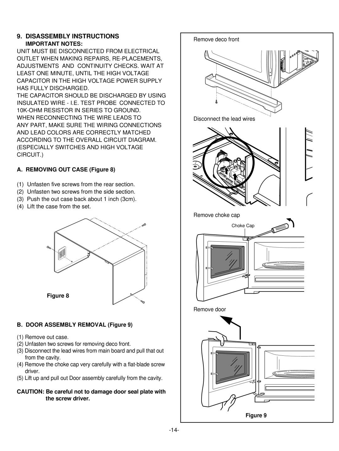
A. REMOVING OUT CASE (Figure 8)
(1)Unfasten five screws from the rear section.
(2)Unfasten two screws from the side section.
(3)Push the out case back about 1 inch (3cm).
(4)Lift the case from the set.
Figure 8
B. DOOR ASSEMBLY REMOVAL (Figure 9)
(1)Remove out case.
(2)Unfasten two screws for removing deco front.
(3)Disconnect the lead wires from main board and pull that out from the cavity.
(4)Remove the choke cap very carefully with a
(5)Lift up and pull out Door assembly carefully from the cavity.
CAUTION: Be careful not to damage door seal plate with the screw driver.
Remove deco front |
Disconnect the lead wires |
Remove choke cap |
Choke Cap |
Remove door |
Figure 9 |
