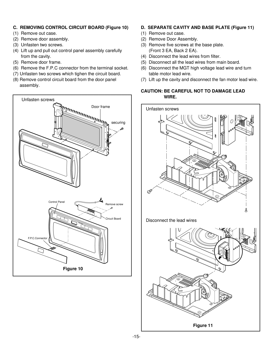
C.REMOVING CONTROL CIRCUIT BOARD (Figure 10)
(1) Remove out case.
(2) Remove door assembly.
(3) Unfasten two screws.
(4) Lift up and pull out control panel assembly carefully from the cavity.
(5) Remove door frame.
(6) Remove the F.P.C connector from the terminal socket.
(7) Unfasten two screws which tighen the circuit board.
(8) Remove control circuit board from the door panel assembly.
Unfasten screws |
Door frame |
securing |
Control Panel |
Remove screw |
Circuit Board |
F.P.C.Connector |
Figure 10 |
D.SEPARATE CAVITY AND BASE PLATE (Figure 11)
(1) Remove out case.
(2) Remove Door Assembly.
(3) Remove five screws at the base plate. (Front 3 EA, Back 2 EA).
(4) Disconnect the lead wires from filter.
(5) Disconnect all the lead wires from main board.
(6) Disconnect the MGT high voltage lead wire and turn table motor lead wire.
(7) Lift up the cavity and disconnect the fan motor lead wire.
CAUTION: BE CAREFUL NOT TO DAMAGE LEAD
WIRE. |
Unfasten screws |
Disconnect the lead wires |
Figure 11 |