Manuals
/
LG Electronics
/
Computer Equipment
/
Laptop
LG Electronics
LS70
service manual
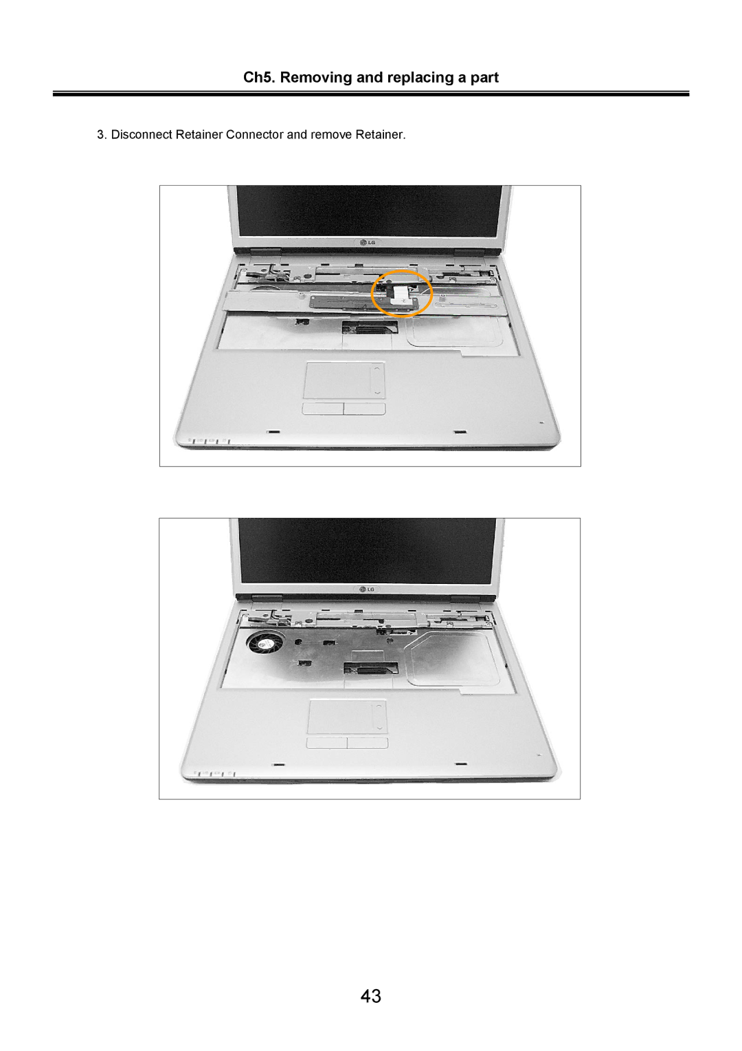
Disconnect Retainer Connector and remove Retainer
Models:
LS70
1
44
94
94
Download
94 pages
13.87 Kb
41
42
43
44
45
46
47
48
Specifications
Before replacing parts
Ch4. Symptom-to-part index
FAN Assembly
Page 44
Image 44
Ch5. Removing and replacing a part
3. Disconnect Retainer Connector and remove Retainer.
43
Page 43
Page 45
Page 44
Image 44
Page 43
Page 45
Contents
LS70 LG Electronics
Page
„ Strategy for replacing a hard-disk drive
Ch1. Service information
Before replacing parts
Ch1. Service information Safety notices
Ch1. Service information Safety information „ General safety
Ch1. Service information „ Electrical safety
Ch1. Service information
Ch1. Service information „ Safety inspection guide
„ Grounding requirements
Ch1. Service information Laser compliance statement
Backup Standby RTC battery safety information
Important Notes
Ch1. Service information Read this first
„ What to do first
Followings are not covered under warranty
Ch2. Locations
„ Front view
Ch2. Locations „ Rear view
„ Left view
„ Right view
Security key hole Kensington Lock
„ Specification
Ch3. System information
Ch3. System information „ System Block Diagram
Ch3. System information „ Fn key combinations
Ch3. System information „ Status indicators
System status indicators show the status of the computer
Ch3. System information „ Bios Flash
Ch3. System information „ How to update flash ROM in Windows
Ch3. System information
Ch3. System information „ Bios Setup
Ch3. System information „ Using the keys
Ch3. System information „ Main menu
Ch3. System information „ Advanced menu
„ Security menu
Ch3. System information „ Boot menu
„ Exit menu
Ch4. Symptom-to-part index
„ Power system checkout
Ch4. Symptom-to-part index
Ch4. Symptom-to-part index
Terminal Voltage V dc Ground
Ch4. Symptom-to-part index „ Numeric error codes
Symptom / Error FRU or action, in sequence
DMA test failed System board 02F6
02F7
Ch4. Symptom-to-part index „ Error message
Ch4. Symptom-to-part index „ LCD-related symptoms
Ch4. Symptom-to-part index „ Indeterminate problems
Removing and replacing a part FRU
Ch5. Removing and replacing a part
Ch5. Removing and replacing a part Battery Pack
Ch5. Removing and replacing a part Hard Disk Drive
Ch5. Removing and replacing a part Wireless LAN Card
Ch5. Removing and replacing a part Keyboard
1SZZBA4097A
Disconnect Keyboard Connector and remove Keyboard
Ch5. Removing and replacing a part Retainer
Disconnect Retainer Connector and remove Retainer
Ch5. Removing and replacing a part Keyboard Plate
Ch5. Removing and replacing a part FAN Assembly
Ch5. Removing and replacing a part Hinge Cover
Ch5. Removing and replacing a part Display Module
Remove Display Module
Ch5. Removing and replacing a part 110 0 Key Deck
1SZZBZ4014A
Ch5. Removing and replacing a part Optical Disk Drive
Ch5. Removing and replacing a part Audio Board
Ch5. Removing and replacing a part HDD Cover Block L
Ch5. Removing and replacing a part Hinge Frame L
Ch5. Removing and replacing a part Main Board
Ch5. Removing and replacing a part
Ch5. Removing and replacing a part
Ch5. Removing and replacing a part Video Board
1SZZBA4080F
Ch5. Removing and replacing a part
1SZZBZ3002W
Ch5. Removing and replacing a part
1SZZBA4017A
Part lists
Ch6. Part lists
400MHZ DDR2 Sdram with 32MX16 NMEM1
Common Bezel for Bran NB-PC HTA05
HFC07
Oversea EXPORT, Slim Type HFC11
HFD03
HFM20
Exploded View
HUNTER-FULL 15 Inch Cover Rear Assy
Exploded View
KUBNKM095A Alps Inverter
DAC-08B073 Delta HUNTER-TL 15 Inch OZ1060S
KUBNKM094A Alps Inverter
DAC-08B072 Delta Inverter
Exploded View
ISP Style B WVA
ISP Style B WVA P3 Plant
WVA ISP Style B
PLATE, Display Rear Hunter 150 Full
Case Assy, Front
Exploded View
HYS64T32000HDL-5-A Infineon 200P Sodimm BK
DDR2 Sdram with 32MX16
64MX64 400MHZ DDR2 Sdram with 32MX16
32MX64 533MHZ DDR2 Sdram with 32MX16
RH80536GE0362M LG Intel 478P Ufcpga Tray NT CPU PENTIUM-M
N HUNTER-FULL 15 Inch Bottom Case Assy 150F
HUNTER-FULL 15 Inch MG Hinge ,FRAME Left
HUNTER-FULL 15 Inch Hinge Frame Assy Right
Exploded View
HUNTER-WIDE 15.4 Inch HDD SUS 17.1W, 15F
MHT2040AT PL Fujitsu 40GB Eide Inner ZEBRA/MACKINLEY/K2
HTS424040M9AT00 Hgst 40GB Eide Inner Mckinly 4200RPM
MHT2060AT PL Fujitsu 60GB Eide Inner ZEBRA/MCKINLEY/K2
FAN Assembly
HUNTER-WIDE 15.4 Inch Pcabs HDD Block
Exploded View
HUNTER-FULL 15 Inch KBD Deck Total Assy
HUNTER-FULL Plate KBD Assy
Centrino Label NT 252352-002 Intel
POP Label LS70 PM IPS for Domestic
HUNTER-FULL 15 Inch Speaker Total Assy
HUNTER-WIDE 15.4 Inch Pcabs KBD Deck BUTTON, Touchpad
Exploded View
HUNTER-F LG-IBM OKI Korea KEY
HUNTER-F LG-IBM OKI English KEY
Taiwan Hunter F OKI 87KEY
Russian Hunter F OKI 86KEY
Exploded View
4800MAH 3S-2P LGC LI-ION Cylinderical HUNTER-ALL Cell LGC
PF8B1CIJ10A-060 Longwell Gost 1830MM 3PIN CONN. Black
SP-022+IS-034+H05VV-F3G I-SHENG Gost 1800MM 3P CONN. Black
PL8B1S3J10A-060 Longwell SAA 1830MM 3PIN Conn Black
SP-502B+H05VV-F+IS-034 I-SHENG SAA 1830MM 3PIN CONN. Black
ID Label Hunter 15T China from Lgeks
ID Label Hunter 15T Lgeks Made in China
ID Label Hunter 15T China from Lgept
Exploded View
Screw M2.5 * L8.0 hinge
Top
Page
Image
Contents