Installation
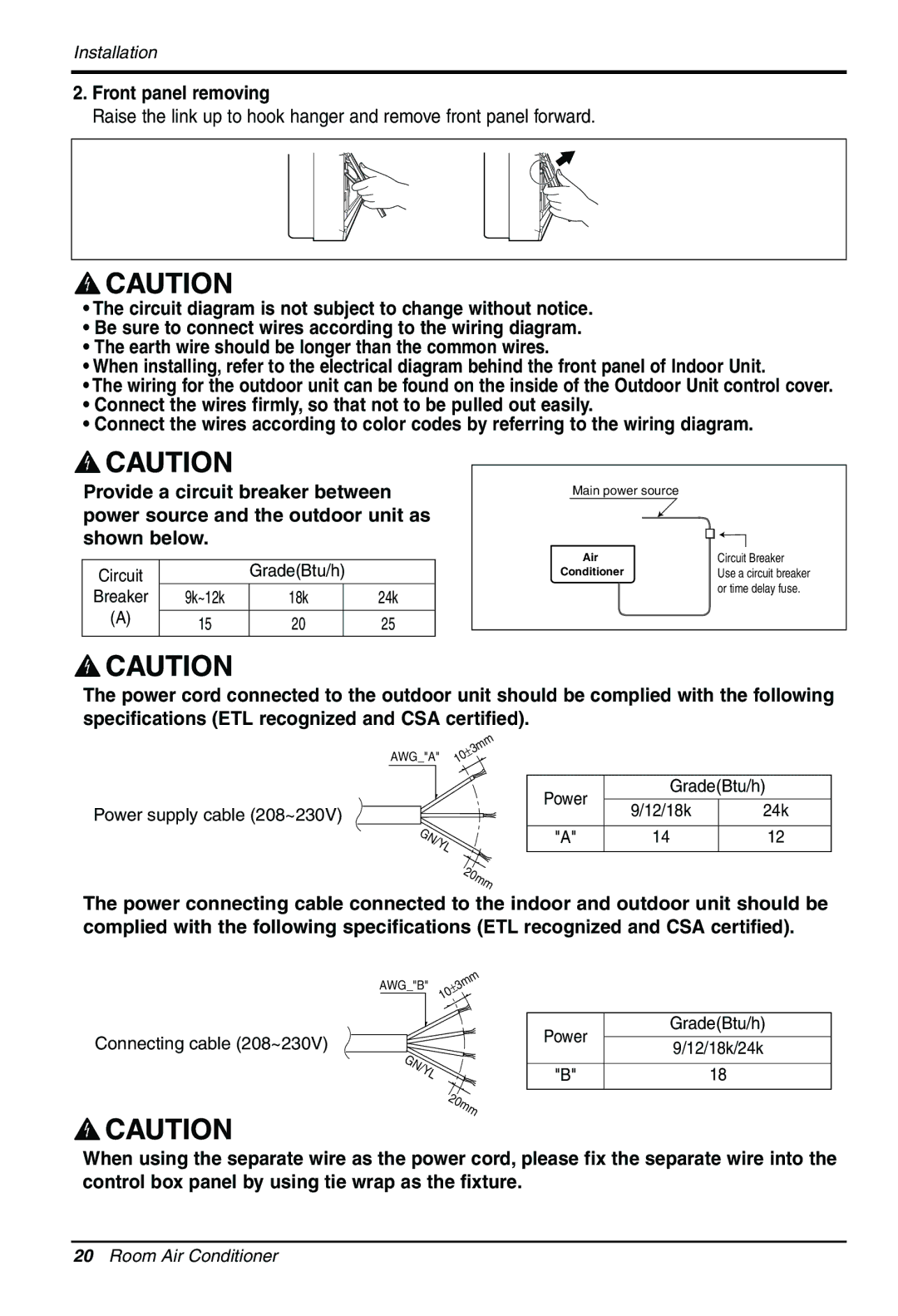
2.Front panel removing
Raise the link up to hook hanger and remove front panel forward.
•The circuit diagram is not subject to change without notice.
•Be sure to connect wires according to the wiring diagram.
•The earth wire should be longer than the common wires.
•When installing, refer to the electrical diagram behind the front panel of Indoor Unit.
•The wiring for the outdoor unit can be found on the inside of the Outdoor Unit control cover.
•Connect the wires firmly, so that not to be pulled out easily.
•Connect the wires according to color codes by referring to the wiring diagram.
Provide a circuit breaker between power source and the outdoor unit as shown below.
Circuit |
| Grade(Btu/h) |
| |
Breaker | 9k~12k | 18k |
| 24k |
(A) | 15 | 20 |
| 25 |
|
| |||
|
|
|
|
|
Main power source |
|
Air | Circuit Breaker |
Conditioner | Use a circuit breaker |
| or time delay fuse. |
The power cord connected to the outdoor unit should be complied with the following specifications (ETL recognized and CSA certified).
AWG_"A" | ±3mm |
10 |
Power supply cable (208~230V) ![]() GN/YL
GN/YL
20mm
Power | Grade(Btu/h) | ||
9/12/18k | 24k | ||
| |||
|
|
| |
"A" | 14 | 12 | |
|
|
| |
The power connecting cable connected to the indoor and outdoor unit should be complied with the following specifications (ETL recognized and CSA certified).
AWG_"B" | ±3mm |
| 10 |
Connecting cable (208~230V) |
|
GN/YL |
|
| 20mm |
Grade(Btu/h)
Power
9/12/18k/24k
"B" | 18 |
When using the separate wire as the power cord, please fix the separate wire into the control box panel by using tie wrap as the fixture.
20Room Air Conditioner