External Control Device Setup
-Connect the
-Connect the serial port of the control device to the
-
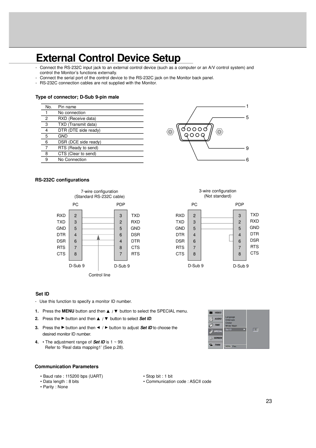
Type of connector; D-Sub 9-pin male
No. Pin name
1No connection
2RXD (Receive data)
3TXD (Transmit data)
4DTR (DTE side ready)
5GND
6DSR (DCE side ready)
7RTS (Ready to send)
8CTS (Clear to send)
9No Connection
RS-232C configurations
(Standard
| PC |
|
| PDP |
| ||
RXD |
|
|
|
|
|
| TXD |
2 |
|
|
| 3 |
| ||
TXD | 3 |
|
|
| 2 |
| RXD |
|
|
|
| ||||
GND | 5 |
|
|
| 5 |
| GND |
|
|
|
| ||||
DTR | 4 |
|
|
| 6 |
| DSR |
|
|
|
| ||||
DSR | 6 |
|
|
| 4 |
| DTR |
|
|
|
| ||||
RTS | 7 |
|
|
| 8 |
| CTS |
|
|
|
| ||||
CTS | 8 |
|
|
| 7 |
| RTS |
|
|
|
|
|
|
|
|
|
|
| |||||
|
|
|
|
|
| ||
|
|
| Control line |
| |||
1
5
9
6
(Not standard)
| PC |
| PDP |
| ||
RXD |
|
|
|
|
| TXD |
2 |
|
| 3 |
| ||
TXD | 3 |
|
| 2 |
| RXD |
|
|
| ||||
GND | 5 |
|
| 5 |
| GND |
|
|
| ||||
DTR | 4 |
|
| 4 |
| DTR |
|
|
| ||||
DSR | 6 |
|
| 6 |
| DSR |
|
|
| ||||
RTS | 7 |
|
| 7 |
| RTS |
CTS | 8 |
|
| 8 |
| CTS |
|
|
|
|
|
|
|
|
| |||||
Set ID
- Use this function to specify a monitor ID number.
1.Press the MENU button and then D / E button to select the SPECIAL menu.
2.Press the G button and then D / E button to select Set ID.
3.Press the G button and then F / G button to adjust Set ID to choose the desired monitor ID number.
4.• The adjustment range of Set ID is 1 ~ 99.
Refer to ‘Real data mapping1’ (See p.28).
VIDEO
AUDIO
TIME
SPECIAL
SCREEN
TWIN
Language
Child lock
Orbiter
White Wash
Set ID | G |
MENU Prev.
1
Communication Parameters
• Baud rate : 115200 bps (UART) | • Stop bit : 1 bit |
• Data length : 8 bits | • Communication code : ASCII code |
• Parity : None |
|
23