Installation and Configuration
5.1.3Installing the Adjustable Rack-Mount Kit—Sold Separately
This kit contains parts needed to mount several different models of UPS and external battery cabi- nets into
Parts included are:
Item | Quantity |
|
|
Rear bracket members | 2 |
|
|
Front bracket members | 2 |
|
|
Inner bracket members | 2 |
|
|
M4 x 8mm machine screws | 16 |
|
|
M4 locking hex nuts | 8 |
|
|
M5 x 16 mm machine screws | 12 |
|
|
Grease packet. | 1 |
|
|
Tools needed for installation are:
•one Phillips screwdriver
•one 7mm wrench
The adjustable
To install the rack mount brackets:
1.Unpack two (2)
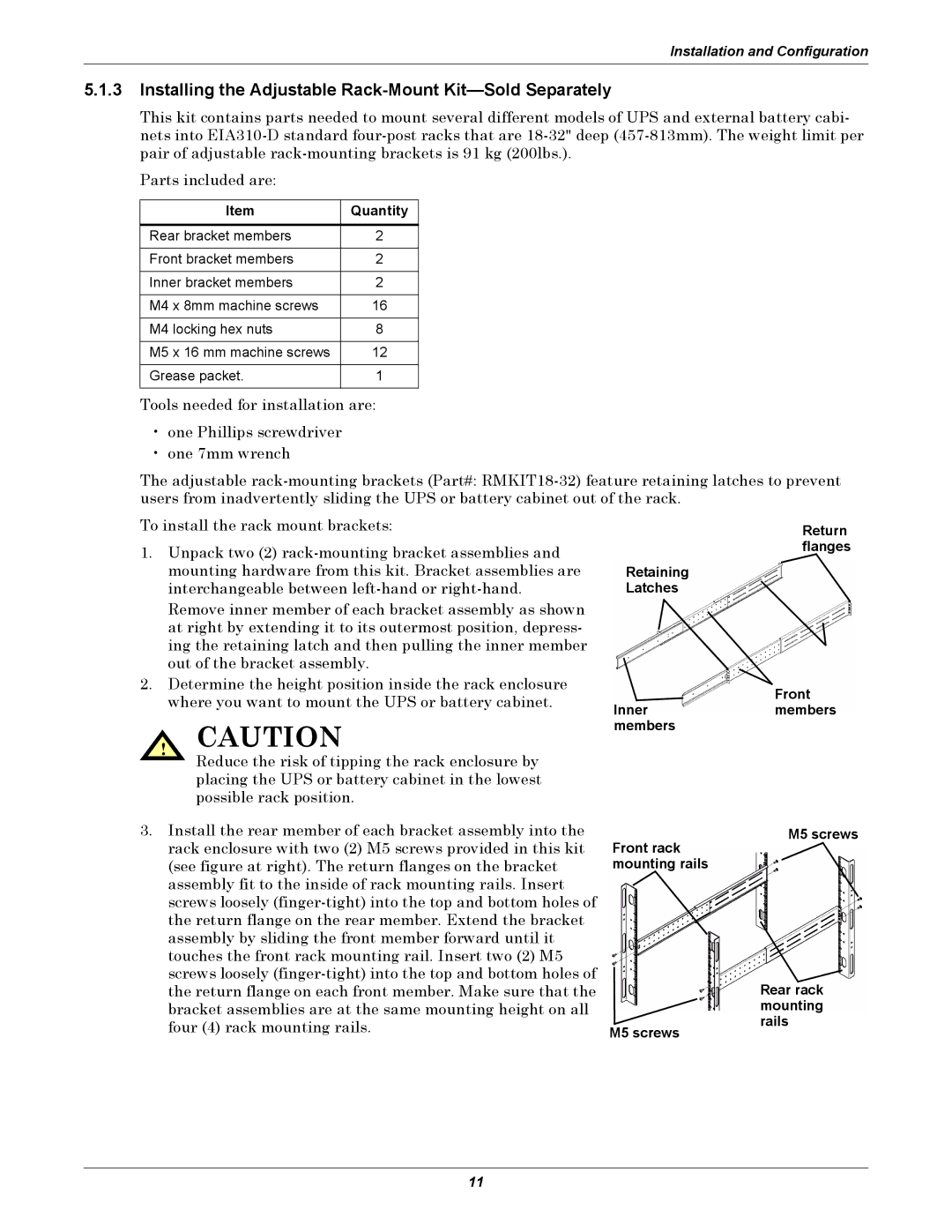
Remove inner member of each bracket assembly as shown at right by extending it to its outermost position, depress- ing the retaining latch and then pulling the inner member out of the bracket assembly.
2.Determine the height position inside the rack enclosure where you want to mount the UPS or battery cabinet.
! CAUTION
Reduce the risk of tipping the rack enclosure by placing the UPS or battery cabinet in the lowest possible rack position.
Return flanges
Retaining
Latches
Front
Innermembers members
3. Install the rear member of each bracket assembly into the |
rack enclosure with two (2) M5 screws provided in this kit |
(see figure at right). The return flanges on the bracket |
assembly fit to the inside of rack mounting rails. Insert |
screws loosely |
the return flange on the rear member. Extend the bracket |
assembly by sliding the front member forward until it |
touches the front rack mounting rail. Insert two (2) M5 |
screws loosely |
M5 screws
Front rack mounting rails
the return flange on each front member. Make sure that the |
bracket assemblies are at the same mounting height on all |
four (4) rack mounting rails. |
M5 screws
Rear rack mounting rails
11