Connecting the UPS Power cables
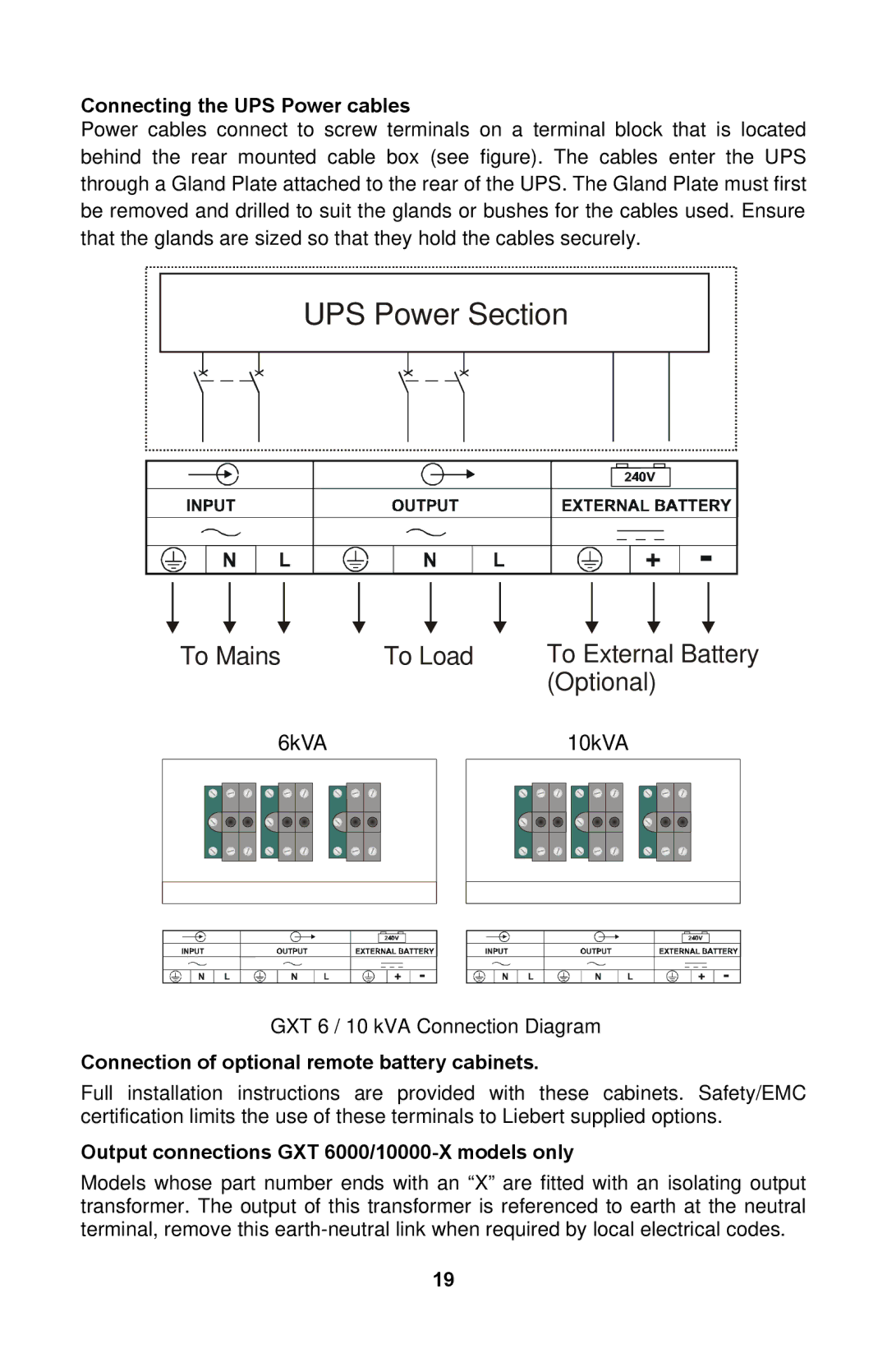
Power cables connect to screw terminals on a terminal block that is located behind the rear mounted cable box (see figure). The cables enter the UPS through a Gland Plate attached to the rear of the UPS. The Gland Plate must first be removed and drilled to suit the glands or bushes for the cables used. Ensure that the glands are sized so that they hold the cables securely.
UPS Power Section
To Mains | To Load | To External Battery |
|
| (Optional) |
6kVA |
10kVA |
GXT 6 / 10 kVA Connection Diagram
Connection of optional remote battery cabinets.
Full installation instructions are provided with these cabinets. Safety/EMC certification limits the use of these terminals to Liebert supplied options.
Output connections GXT 6000/10000-X models only
Models whose part number ends with an “X” are fitted with an isolating output transformer. The output of this transformer is referenced to earth at the neutral terminal, remove this
19