COMMUNICATIONS INTERFACE PORT
The UPStation GXT UPS contains a standard
PIN |
| ASSIGNMENT DESCRIPTION |
|
|
|
|
|
|
|
1 |
| Low Battery (open collector) |
|
|
|
|
|
|
|
2 |
| UPS TxD (typical |
|
|
|
|
|
|
|
3 |
| UPS RxD (typical |
|
|
|
|
|
|
|
4 |
| Remote Shutdown | |||||||
5 |
| Common |
|
|
|
|
|
|
|
6 |
| Remote Shutdown (short to pin 5) | UPS mode (all modes) of operation | ||||||
7 |
| Low Battery (open emitter) |
|
|
|
|
|
|
|
8 |
| Mains Fail (open emitter) |
|
|
|
|
|
|
|
9 |
| Mains Fail (open collector) |
|
|
|
|
|
|
|
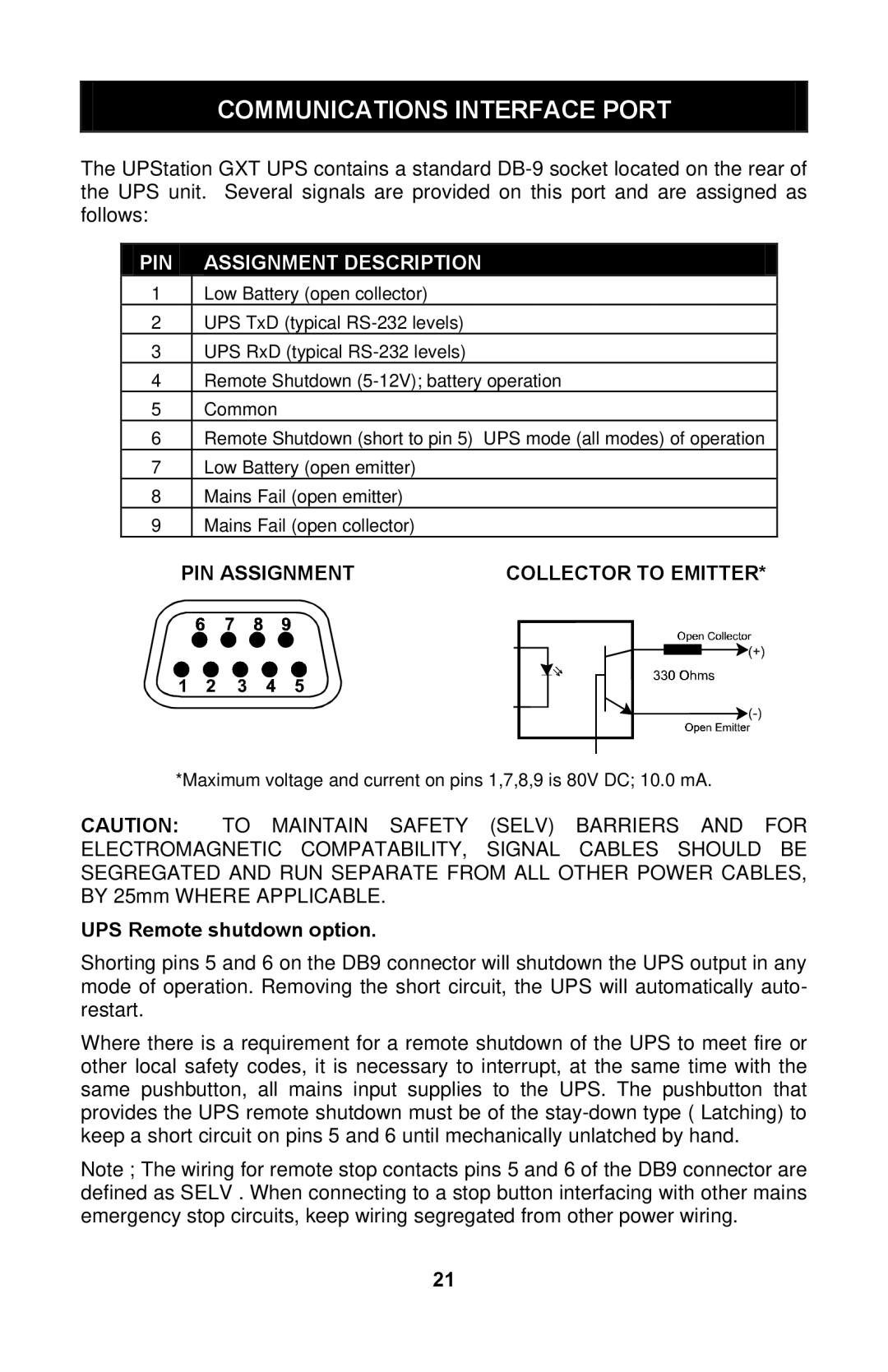
| PIN ASSIGNMENT | COLLECTOR TO EMITTER* | |||||||
|
|
|
|
|
|
|
|
|
|
|
|
|
|
|
|
|
|
|
|
|
|
|
|
|
|
|
|
|
|
|
|
|
|
|
|
|
|
|
|
|
|
|
|
|
|
|
|
|
|
|
|
|
|
|
|
|
|
|
|
*Maximum voltage and current on pins 1,7,8,9 is 80V DC; 10.0 mA.
CAUTION: TO MAINTAIN SAFETY (SELV) BARRIERS AND FOR ELECTROMAGNETIC COMPATABILITY, SIGNAL CABLES SHOULD BE SEGREGATED AND RUN SEPARATE FROM ALL OTHER POWER CABLES, BY 25mm WHERE APPLICABLE.
UPS Remote shutdown option.
Shorting pins 5 and 6 on the DB9 connector will shutdown the UPS output in any mode of operation. Removing the short circuit, the UPS will automatically auto- restart.
Where there is a requirement for a remote shutdown of the UPS to meet fire or other local safety codes, it is necessary to interrupt, at the same time with the same pushbutton, all mains input supplies to the UPS. The pushbutton that provides the UPS remote shutdown must be of the
Note ; The wiring for remote stop contacts pins 5 and 6 of the DB9 connector are defined as SELV . When connecting to a stop button interfacing with other mains emergency stop circuits, keep wiring segregated from other power wiring.
21