Introduction
1.3Major Components
The following is a general description of each compo- nent and its functions. Please review this section carefully, as it will give you a better understanding as to how the Nfinity operates.
1.3.1Unit Frame
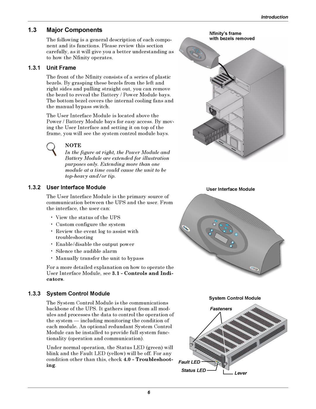
The front of the Nfinity consists of a series of plastic bezels. By grasping these bezels from the left and right sides and pulling straight out, you can remove the bezel to reveal the Battery / Power Module bays. The bottom bezel covers the internal cooling fans and the manual bypass switch.
The User Interface Module is located above the Power / Battery Module bays for easy access. By mov- ing the User Interface and setting it on top of the frame, you will see the system control module bays.
NOTE
In the figure at right, the Power Module and Battery Module are extended for illustration purposes only. Extending more than one module at a time could cause the unit to be top-heavy and/or tip.
Nfinity’s frame
with bezels removed
1.3.2 User Interface Module | User Interface Module |
The User Interface Module is the primary source of communication between the UPS and the user. From the interface, the user can:
• View the status of the UPS
• Custom configure the system
• Review the event log to assist with troubleshooting
• Enable/disable the output power
•Silence the audible alarm
•Manually transfer the unit to bypass
For a more detailed explanation on how to operate the User Interface Module, see 3.1 - Controls and Indi- cators.
1.3.3System Control Module
The System Control Module is the communications backbone of the UPS. It gathers input from all mod- ules and processes the data to control the operation of the system — including monitoring the condition of each module. An optional redundant System Control Module can be installed to provide full system func- tionality (operation and communication).
Under normal operation, the Status LED (green) will blink and the Fault LED (yellow) will be off. For any condition other than this, check 4.0 - Troubleshoot- ing.
System Control Module
Fasteners
Fault LED |
Status LED | Lever |
|
6