Chapter 1 | Setting Up the EnCore 420 |
Connecting Cables to the CoreModule 420
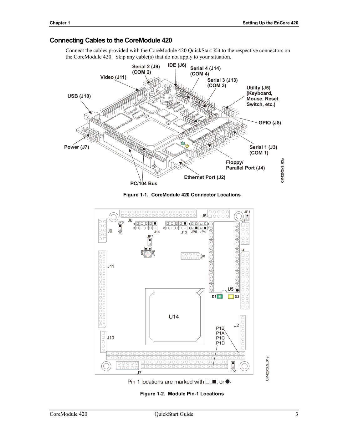
Connect the cables provided with the CoreModule 420 QuickStart Kit to the respective connectors on the CoreModule 420. Skip any cable(s) that do not apply to your situation.
Serial 2 (J9) IDE (J6) (COM 2)
Video (J11)
USB (J10)
Serial 4 (J14) (COM 4)
Serial 3 (J13) (COM 3)
Utility (J5) (Keyboard, Mouse, Reset Switch, etc.)
![]()
![]()
![]()
![]() GPIO (J8)
GPIO (J8)
Power (J7) | Serial 1 (J3) |
| (COM 1) |
Floppy/
Parallel Port (J4)
Ethernet Port (J2)
PC/104 Bus
CM420QkS_03a
Figure 1-1. CoreModule 420 Connector Locations
|
|
|
|
| J5 |
|
| JP1 |
| J6 |
|
|
|
|
|
| |
JP6 |
|
| 4 |
| 2 |
| J3 | |
| 9 |
|
|
|
|
| ||
J9 | 10 | 10 |
| 3 |
| 1 |
|
|
| J14 | J13 | JP5 | JP4 |
|
|
| |
|
| JP7 |
|
|
|
|
|
|
| JP9 | JP8 |
|
|
|
|
| J4 |
|
|
| 1J8 |
|
|
| ||
|
|
|
|
| 2 |
|
|
|
J11 |
|
|
|
|
|
|
|
|
|
|
|
|
|
|
| U5 |
|
|
|
|
|
|
| D1 | D2 |
|
|
|
| U14 |
|
|
|
|
|
|
|
|
|
|
|
| J2 |
|
|
|
|
|
|
| P1B |
| |
J10 |
|
|
|
|
| P1A |
| |
|
|
|
|
| P1C |
| ||
|
|
|
|
|
| P1D |
| |
|
|
|
|
|
|
|
| 01e |
| J7 |
|
|
|
|
| JP2 | CM420QkS |
|
|
|
|
|
|
| ||
| Pin 1 locations are marked with | , | , or . | |||||
|
| |||||||
| Figure |
| ||||||
CoreModule 420 | QuickStart Guide | 3 |