Chapter 1Setting Up the CoreModule 420
|
|
| • Refer to Installing Software, Drivers, and Utilities in Chapter 2 | |
|
|
| and the CoreModule 420 Doc & SW | |
|
|
| information. | |
|
|
|
|
|
21) Install the desired |
| • Locate the desired Operating System (OS) diskette(s), or CD- | ||
| Operating System (OS) | ROM and follow the manufacturer’s instructions for installing | ||
| on the hard disk drive. | the OS and the necessary drivers onto the hard disk drive. | ||
|
|
| • Refer to Note on Hard Drive installation from 11b, page 7. | |
|
|
| For Windows Operating Systems, most of the necessary drivers are | |
|
|
| found on the manufacturer’s installation | |
|
|
| For | |
|
|
| drivers may be found on the manufacturer’s diskette(s) or | |
|
|
| • Refer to Installing Software, Drivers, and Utilities in Chapter 2 | |
|
|
| and the CoreModule 420 software subdirectory on the | |
|
|
| CoreModule 420 Doc & SW | |
|
|
|
|
|
|
|
|
| |
| NOTE | The CoreModule 420 SBC ships from the factory configured only for CRT |
| |
|
| support. Ampro provides LCD/TFT support for flat panels with specific |
| |
|
| resolutions. Refer to the CoreModule 420 Reference Manual, the Release Notes, |
| |
|
| and Virtual Technician on the web site for instructions and additional information |
| |
|
| when customizing the BIOS to a particular flat panel. |
| |
|
|
|
|
|
Table
Jumper # |
| Installed | Removed | ||||
JP1 Serial Port 1 | Enable RS485 Termination | Disable RS485 Termination | |||||
Termination | (Pins | (No jumper) Default setting | |||||
|
|
|
|
| |||
JP2 Serial Port 2 | Enable RS485 Termination | Disable RS485 Termination | |||||
Termination | (Pins | (No jumper) Default setting | |||||
|
|
|
|
|
| ||
JP4 & JP5 |
| Enable Internal BIOS – Normal operation, | Disabled – Won’t Boot | ||||
BIOS/DOC Select | (Pins | (See other positions) | |||||
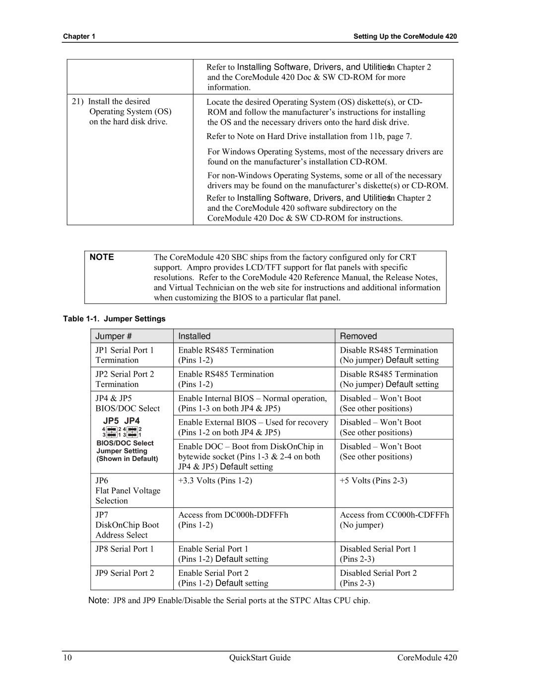
JP5 JP4 |
|
| |||||
Enable External BIOS – Used for recovery | Disabled – Won’t Boot | ||||||
4 |
| 2 4 |
| 2 | (Pins | (See other positions) | |
|
| ||||||
3 |
| 1 |
| 1 | |||
|
| ||||||
BIOS/DOC Select |
|
| |||||
Enable DOC – Boot from DiskOnChip in | Disabled – Won’t Boot | ||||||
Jumper Setting | |||||||
bytewide socket (Pins | (See other positions) | ||||||
(Shown in Default) | |||||||
|
|
|
|
| JP4 & JP5) Default setting |
| |
|
|
|
|
|
| ||
JP6 |
|
|
| +3.3 Volts (Pins | +5 Volts (Pins | ||
Flat Panel Voltage |
|
| |||||
Selection |
|
|
| ||||
|
|
|
|
|
| ||
JP7 |
|
|
| Access from | Access from | ||
DiskOnChip Boot | (Pins | (No jumper) | |||||
Address Select |
|
| |||||
|
|
| |||||
JP8 Serial Port 1 | Enable Serial Port 1 | Disabled Serial Port 1 | |||||
|
|
|
|
| (Pins | (Pins | |
|
|
| |||||
JP9 Serial Port 2 | Enable Serial Port 2 | Disabled Serial Port 2 | |||||
|
|
|
|
| (Pins | (Pins | |
|
|
|
|
|
|
| |
Note: JP8 and JP9 Enable/Disable the Serial ports at the STPC Altas CPU chip.
10 | QuickStart Guide | CoreModule 420 |