Operating Instructions
3.5.7Module Replacement
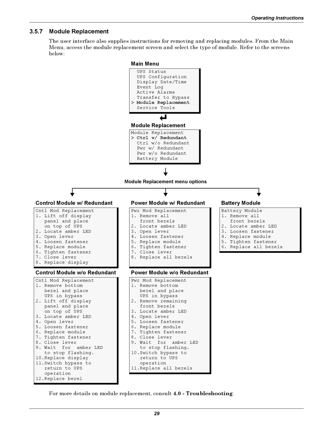
The user interface also supplies instructions for removing and replacing modules. From the Main Menu, access the module replacement screen and select the type of module. Refer to the screens below:
Main Menu
UPS Status
UPS Configuration
Display Date/Time
Event Log
Active Alarms
Transfer to Bypass
>Module Replacement Service Tools
Module Replacement
Module Replacement
>Ctrl w/ Redundant Ctrl w/o Redundant Pwr w/ Redundant Pwr w/o Redundant Battery Module
Module Replacement menu options
Control Module w/ Redundant
Cntl Mod Replacement
1.Lift off display panel and place on top of UPS
2.Locate amber LED
3.Open lever
4.Loosen fastener
5.Replace module
6.Tighten fastener
7.Close lever
8.Replace display
Control Module w/o Redundant
Cntl Mod Replacement
1.Remove bottom bezel and place UPS in bypass
2.Lift off display panel and place on top of UPS
3.Locate amber LED
4.Open lever
5.Loosen fastener
6.Replace module
7.Tighten fastener
8.Close lever
9.Wait for amber LED to stop flashing.
10.Replace display 11.Switch bypass to return to UPS
operation 12.Replace bezel
Power Module w/ Redundant
Pwr Mod Replacement
1.Remove all front bezels
2.Locate amber LED
3.Open lever
4.Loosen fastener
5.Replace module
6.Tighten fastener
7.Close lever
8.Replace all bezels
Power Module w/o Redundant
Pwr Mod Replacement
1.Remove bottom bezel and place UPS in bypass
2.Remove remaining front bezels
3.Locate amber LED
4.Open lever
5.Loosen fastener
6.Replace module
7.Tighten fastener
8.Close lever
9.Wait for amber LED to stop flashing.
10.Switch bypass to
return to UPS operation
11.Replace all bezels
Battery Module
Battery Module
1.Remove all front bezels
2.Locate amber LED
3.Loosen fastener
4.Replace module
5.Tighten fastener
6.Replace all bezels
For more details on module replacement, consult 4.0 - Troubleshooting.
29