211111 7085270 - 00 specifications
The Liebherr 211111 7085270 - 00 is a robust piece of machinery that embodies cutting-edge technology and innovative engineering, primarily designed for applications within the construction and heavy equipment sectors. This model is renowned for its durability, versatility, and exceptional performance under demanding conditions.Equipped with an efficient and powerful engine, the Liebherr 211111 7085270 - 00 delivers optimal performance while adhering to stringent emission standards. This not only ensures compliance with environmental regulations but also contributes to lower fuel consumption and operational costs. The engine is complemented by advanced hydraulic systems, which enhance the overall efficiency of the machine, allowing for seamless operation in various tasks such as lifting, moving, and precise handling of materials.
One of the standout features of this model is its sophisticated operator interface. The intuitive controls and ergonomic design ensure that operators can manage the machine with ease, improving productivity and reducing fatigue during prolonged usage. The cab design prioritizes visibility and comfort, featuring large windows and adjustable seating, providing operators with an unobstructed view of the worksite.
The Liebherr 211111 7085270 - 00 also incorporates advanced technological features such as telematics and real-time monitoring systems. These technologies enable fleet managers to track the equipment’s performance, schedule maintenance, and reduce downtime. The integration of telematics offers insights into fuel efficiency, working hours, and operational parameters, allowing for data-driven decision-making to enhance productivity and longevity.
In addition to its technological advancements, the Liebherr 211111 7085270 - 00 is built with high-quality materials that ensure longevity and can withstand harsh job site conditions. Its components are designed for easy maintenance and serviceability, minimizing interruption to workflows.
Overall, the Liebherr 211111 7085270 - 00 is a testament to Liebherr's commitment to quality, innovation, and customer satisfaction. With its impressive performance characteristics, state-of-the-art technology, and user-centric design, this machine stands as a reliable solution for contractors looking to enhance their operational efficiency and productivity in various applications. Whether used in construction, excavation, or other heavy-duty tasks, the Liebherr 211111 7085270 - 00 is engineered to exceed expectations and meet the challenges of modern construction needs.

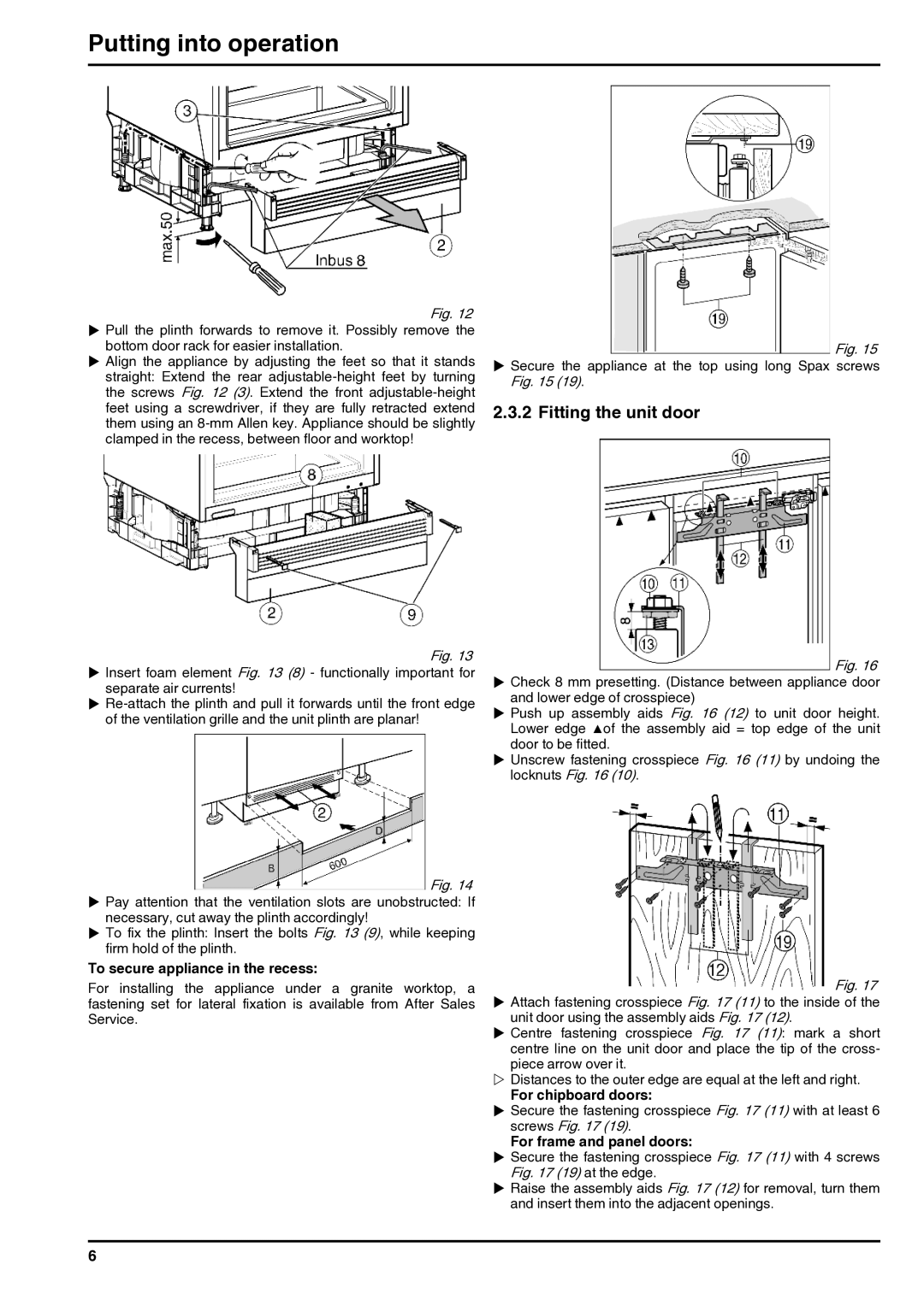
 Fig. 14
  Fig. 15
  Fig. 16
  Fig. 17