8 |
3/8 X |
27 |
42 |
SHAFT |
45 |
5 |
51 |
STOP |
POST |
2 |
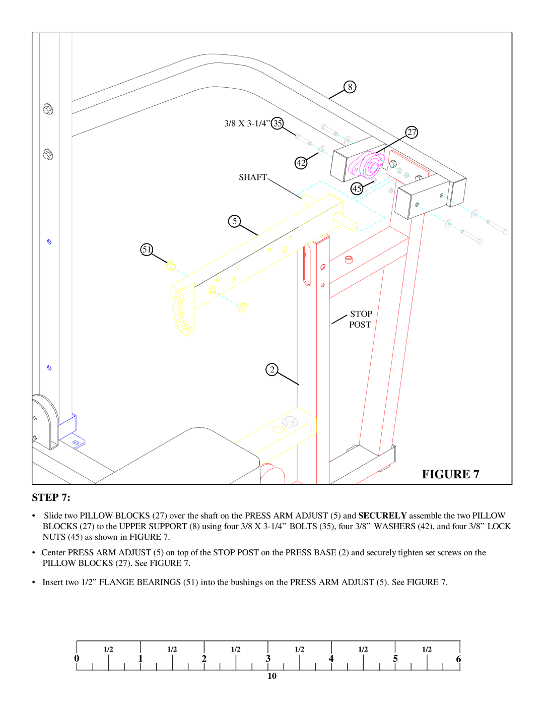
FIGURE 7 |
STEP 7:
•Slide two PILLOW BLOCKS (27) over the shaft on the PRESS ARM ADJUST (5) and SECURELY assemble the two PILLOW BLOCKS (27) to the UPPER SUPPORT (8) using four 3/8 X
•Center PRESS ARM ADJUST (5) on top of the STOP POST on the PRESS BASE (2) and securely tighten set screws on the PILLOW BLOCKS (27). See FIGURE 7.
•Insert two 1/2” FLANGE BEARINGS (51) into the bushings on the PRESS ARM ADJUST (5). See FIGURE 7.
1/2
1/2
1/2
1/2
1/2
1/2
0
1 | 2 | 3 | 4 | 5 |
|
|
|
|
|
10
6
