9
45
2
19 | 38 3/8 X 2” |
21
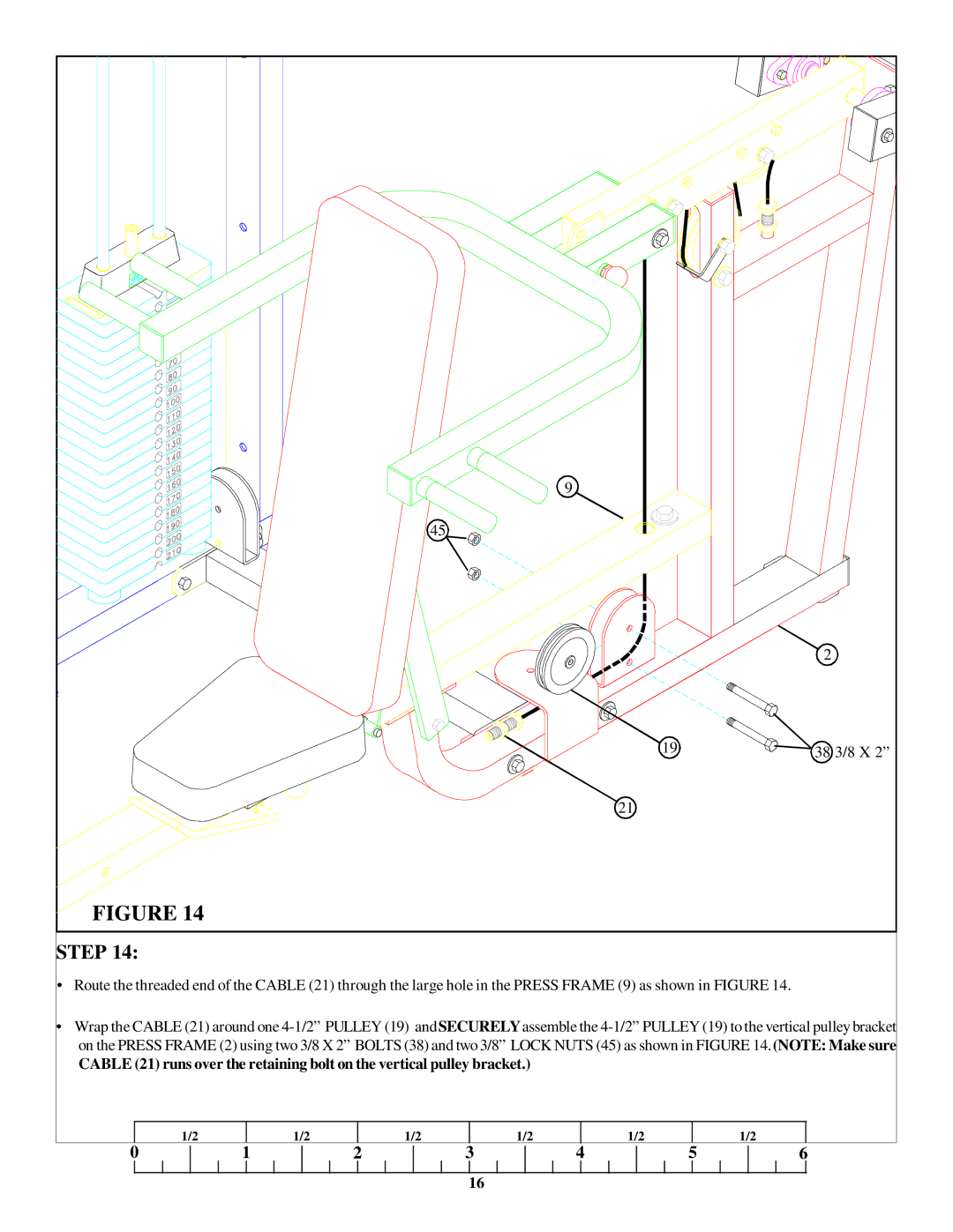
FIGURE 14
STEP 14:
•Route the threaded end of the CABLE (21) through the large hole in the PRESS FRAME (9) as shown in FIGURE 14.
•Wrap the CABLE (21) around one
CABLE (21) runs over the retaining bolt on the vertical pulley bracket.)
1/2
1/2
1/2
1/2
1/2
1/2
0
1 | 2 | 3 | 4 | 5 |
|
|
|
|
|
16
6