3
1/2 X 6-1/2” 30
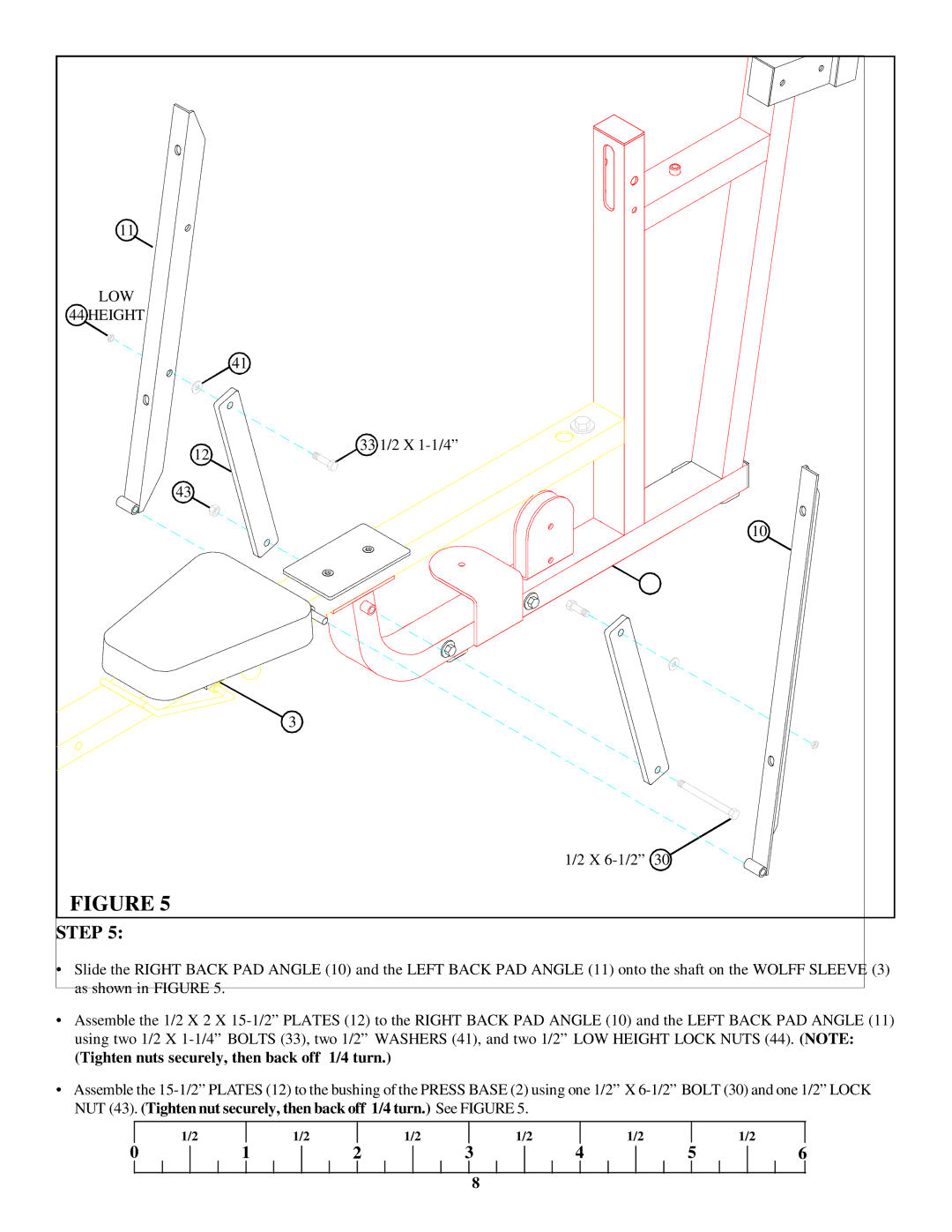
FIGURE 5
STEP 5:
•Slide the RIGHT BACK PAD ANGLE (10) and the LEFT BACK PAD ANGLE (11) onto the shaft on the WOLFF SLEEVE (3) as shown in FIGURE 5.
•Assemble the 1/2 X 2 X 15-1/2” PLATES (12) to the RIGHT BACK PAD ANGLE (10) and the LEFT BACK PAD ANGLE (11) using two 1/2 X 1-1/4” BOLTS (33), two 1/2” WASHERS (41), and two 1/2” LOW HEIGHT LOCK NUTS (44). (NOTE: (Tighten nuts securely, then back off 1/4 turn.)
•Assemble the 15-1/2”PLATES (12) to the bushing of the PRESS BASE (2) using one 1/2” X 6-1/2” BOLT (30) and one 1/2” LOCK NUT (43). (Tighten nut securely, then back off 1/4 turn.) See FIGURE 5.

