4 | |
45 | |
| 5 |
| 19 |
| 52 |
45 | 21 |
45 | |
| 19 |
| 37 3/8 X 2-3/4” |
42 | 53 |
|
| 52 |
| 57 |
19 | 34 3/8 X 3-3/4” |
| 34 3/8 X 3-3/4” |
| 2 |
| FIGURE 13 |
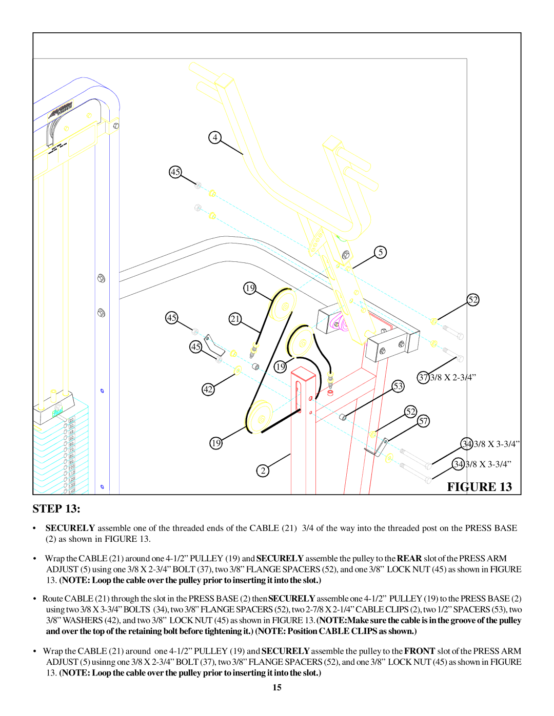
STEP 13:
•SECURELY assemble one of the threaded ends of the CABLE (21) 3/4 of the way into the threaded post on the PRESS BASE
(2)as shown in FIGURE 13.
•Wrap the CABLE (21) around one 4-1/2” PULLEY (19) and SECURELY assemble the pulley to the REAR slot of the PRESS ARM ADJUST (5) using one 3/8 X 2-3/4” BOLT (37), two 3/8” FLANGE SPACERS (52), and one 3/8” LOCK NUT (45) as shown in FIGURE
13.(NOTE: Loop the cable over the pulley prior to inserting it into the slot.)
•Route CABLE (21) through the slot in the PRESS BASE (2) thenSECURELY assemble one 4-1/2” PULLEY (19) to the PRESS BASE (2) using two 3/8 X 3-3/4” BOLTS (34), two 3/8” FLANGE SPACERS (52), two 2-7/8 X 2-1/4” CABLE CLIPS (2), two 1/2” SPACERS (53), two 3/8” WASHERS (42), and two 3/8” LOCK NUT (45) as shown in FIGURE 13.(NOTE:Make sure the cable is in the groove of the pulley and over the top of the retaining bolt before tightening it.) (NOTE: Position CABLE CLIPS as shown.)
•Wrap the CABLE (21) around one 4-1/2”PULLEY (19) and SECURELY assemble the pulley to the FRONT slot of the PRESS ARM ADJUST (5) usinng one 3/8 X 2-3/4” BOLT (37), two 3/8” FLANGE SPACERS (52), and one 3/8” LOCK NUT (45) as shown in FIGURE
13.(NOTE: Loop the cable over the pulley prior to inserting it into the slot.)
15