FIGURE 11 |
4 |
4 |
13 |
12 |
9 |
10 |
2 |
27 |
1 |
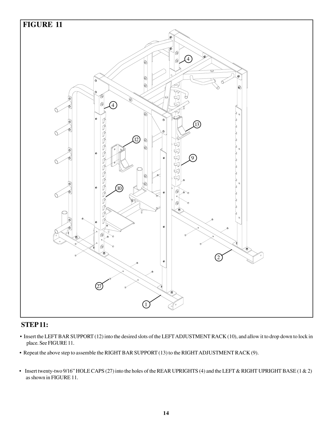
STEP 11:
•Insert the LEFT BAR SUPPORT (12) into the desired slots of the LEFT ADJUSTMENT RACK (10), and allow it to drop down to lock in place. See FIGURE 11.
•Repeat the above step to assemble the RIGHT BAR SUPPORT (13) to the RIGHT ADJUSTMENT RACK (9).
•Insert
14